
Forte L4-2.0L (2010)
Relay Box: Testing and Inspection
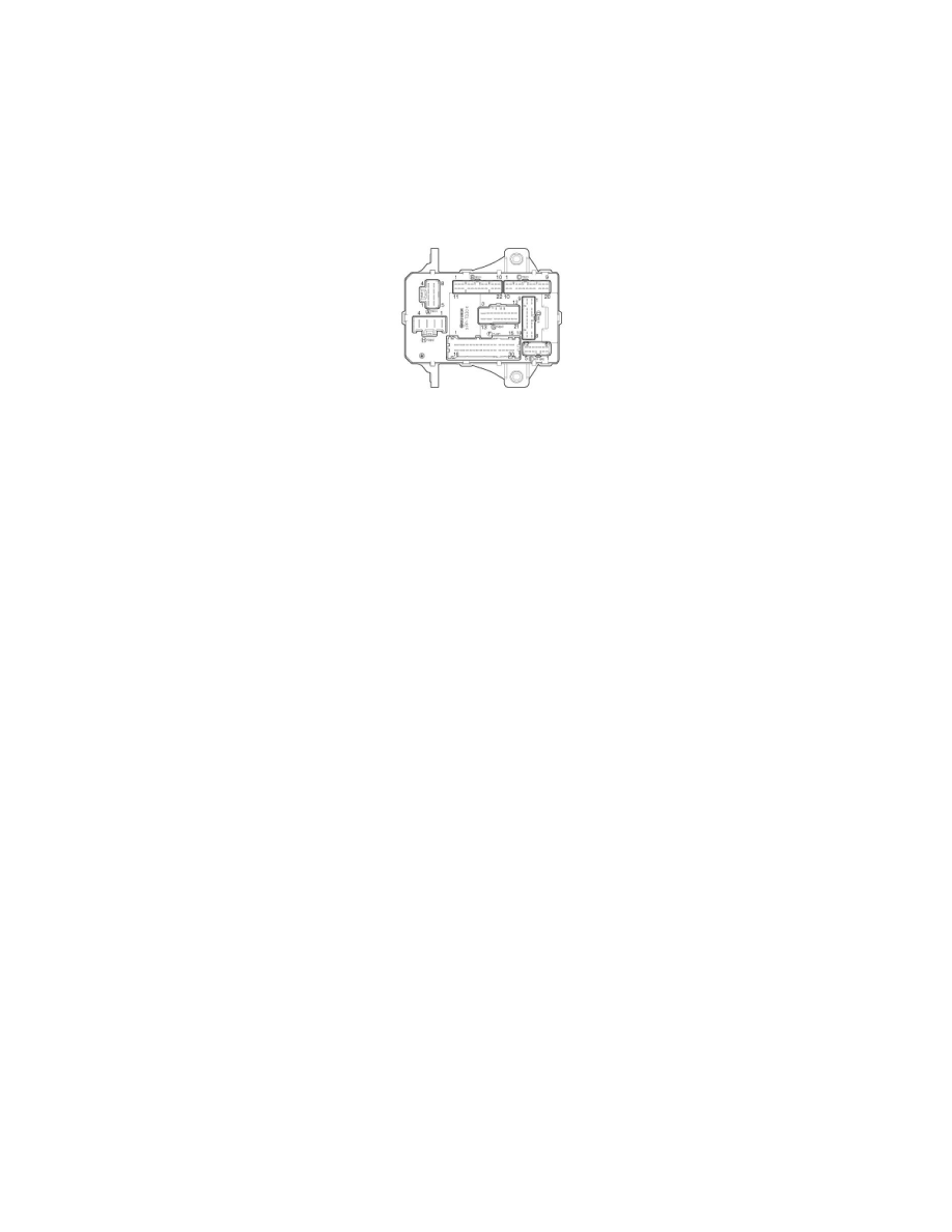
Relay Box (Passenger Compartment)
Inspection
Passenger Compartment Relay
1. Disconnect the negative(-) battery terminal.
2. Remove the crash pad lower panel.
3. Remove the junction box.
Power Window
Check for continuity between the terminals.
1. There should be continuity between the No.2 terminal in the I/P-H and the No.16 or 17 terminal in the I/P-F when power and ground are
connected to the No.2 terminal in the I/P-H and the No.17 terminal in the I/P-B.
2. There should be no continuity between the No.2 terminal in the I/P-H and the No.16 or 17 terminal in the I/P-F when power and ground are
connected to the No.2 terminal in the I/P-H and the No.17 terminal in the I/P-B.
Tail Lamp
Check for continuity between the terminals.
1. There should be continuity between the No.2 terminal in the I/P-H and the No.22(LH) or 6(RH) terminal in the I/P-F when power and ground are
connected to the No.2 terminal in the I/P-H and the No.6 terminal in the I/P-D.
2. There should be no continuity between the No.2 terminal in the I/P-H and the No.15(LH) or 4(RH) terminal in the I/P-G when power and ground
are connected to the No.2 terminal in the I/P-H and the No.6 terminal in the I/P-D.
Trunk Lid Open
Check for continuity between the terminals.
1. There should be continuity between the No.3 terminal in the I/P-H and the No.28 terminal in the I/P-F when power and ground are connected to
the No.3 terminal in the I/P-H and the No.2 terminal in the I/P-D.
2. There should be no continuity between the No.3 terminal in the I/P-H and the No.28 terminal in the I/P-F when power and ground are connected to
the No.3 terminal in the I/P-H and the No.2 terminal in the I/P-F.
Rear Heater
Check for continuity between the terminals.
1. There should be continuity between the No.3 terminal in the I/P-G and the No.2 or 4 terminal in the I/P-F when power and ground are connected
to the No.3 terminal in the I/P-G and the No.16 terminal in the I/P-B.
2. There should be no continuity between the No.3 terminal in the I/P-G and the No.2 or 4 terminal in the I/P-F when power and ground are
connected to the No.3 terminal in the I/P-G and the No.16 terminal in the I/P-B.