
Forte L4-2.0L (2010)
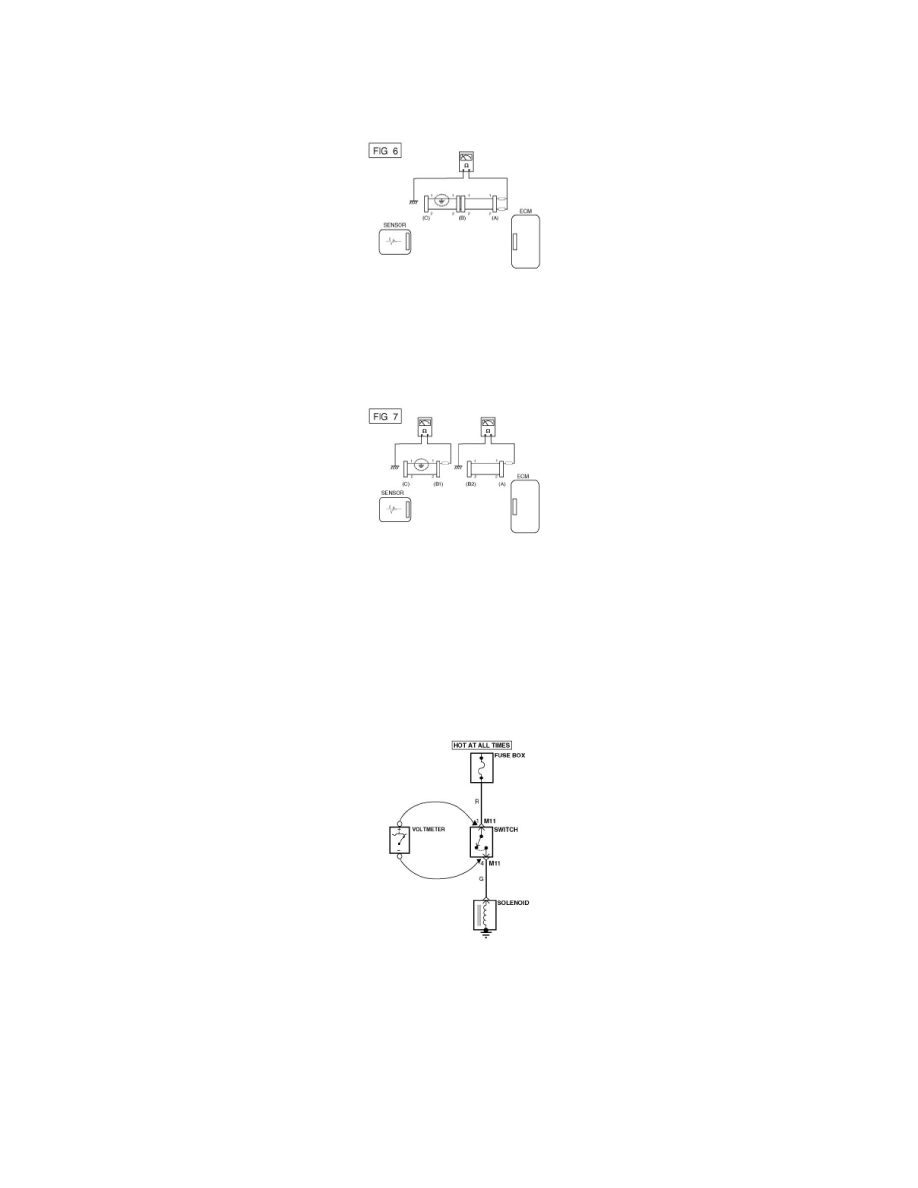
A. Disconnect connectors (A), (C) and measure for resistance between connector (A) and Chassis Ground as shown in [FIG. 6].
The measured resistance of line 1 and 2 in this example is below 1 Ohms and higher than 1MOhms respectively. Specifically the short to
ground circuit is line 1 (Line 2 is normal). To find exact broken point, check the sub line of line 1 as described in the following step.
B. Disconnect connector (B), and measure the resistance between connector (A) and chassis ground, and between (B1) and chassis ground as
shown in [FIG. 7].
The measured resistance between connector (B1) and chassis ground is 1Ohms or less. The short to ground circuit is between terminal 1 of
connector (C) and terminal 1 of connector (B1).
Testing For Voltage Drop
This test checks for voltage drop along a wire, or through a connection or switch.
1) Connect the positive lead of a voltmeter to the end of the wire (or to the side of the connector or switch) closest to the battery.
2) Connect the negative lead to the other end of the wire. (or the other side of the connector or switch)
3) Operate the circuit.
4) The voltmeter will show the difference in voltage between the two points. A difference, or drop of more than 0.1 volts (50mV in 5V circuits),
may indicate a problem. Check the circuit for loose or dirty connections.