
Optima V6-2.7L VIN 4 (2007)
Ignition Switch: Diagram Information and Instructions
Schematic Diagrams
INTRODUCTION
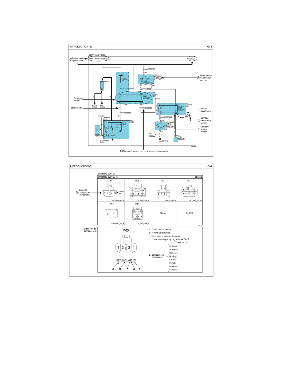
1. Pages by system / Name of Schematic diagram
-
Each page is consisted of circuits by system. This schematic diagram includes the path of electricity flow, connection condition for each
switch, and the function of other relevant circuits at once. It is applicable to real service work.
-
It is very important to understand relevant circuits exactly before troubleshooting diagnosis.
-
Circuits by system depends upon part number and are indicated on schematic diagram index.
2. Connector configuration (components)
-
The connector figure of components in the schematic diagram by system is indicated on the last page of schematic diagram.
-
It shows the front of the connector on the harness side when not to the harness connector. The terminal number on each connector can be
obtained by following the pattern used in (5) connector view and numbering order. Unused terminals are marked with an asterisk (*).
3. Connector configurations (connection between harnesses)
-
When connecting the harness with connector between harnesses, it shows female and male connectors and indicates them on the connector