
Rondo L4-2.4L (2007)
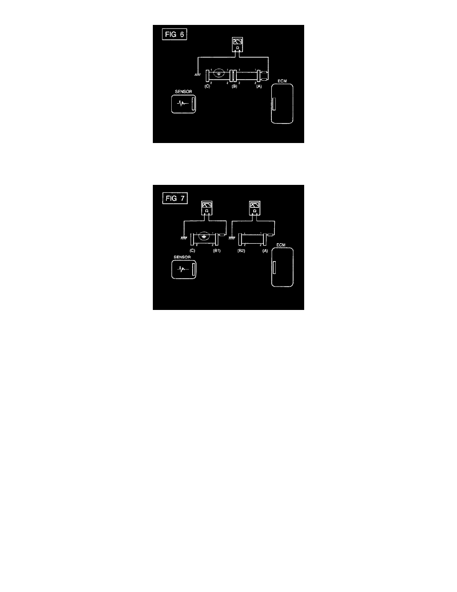
a. Disconnect connectors (A), (C) and measure for resistance between connector (A) and Chassis Ground as shown in [FIG. 6].
The measured resistance of line 1 and 2 in this example is below 1 ohm and higher than 1 Mohm respectively. Specifically the short to
ground circuit is line 1 (Line 2 is normal) To find exact broken point, check the sub line of line 1 as described in the following step
b. Disconnect connector (B), and measure the resistance between connector (A) and chassis ground, and between (B1) and chassis ground as
shown in [FIG. 7].
The measured resistance between connector (B1) and chassis ground is 1 ohm or less. The short to ground circuit is between terminal 1 of
connector (C) and terminal 1 of connector (B1).
Trouble Shooting Instructions
TROUBLESHOOTING INSTRUCTIONS
TROUBLESHOOTING PROCEDURES
The following five-step troubleshooting procedure is recommended.
1. Verify the customer's complaints
Turn on all the components in the problem circuit to check the accuracy of the customer's complaints. Note the symptoms.
Do not begin disassembly or testing until you have narrowed down the probable causes.
2. Read and analyze the schematic diagram
Locate the schematic for the problem circuit. Determine how the circuit is supposed to work by tracing the current paths from the power source
through the system components to ground. If you do not understand how the circuit should work, read the circuit operation text. Also check other
circuits that share with the problem circuit. The name of circuits that share the same fuse, ground, or switch, for example, are referred to on each
diagram. Try to operate any shared circuits you did not check in step 1. If the shared circuit works, the shared wiring is okay, and the cause must
be within the wiring used only by the problem circuit.
It several circuits fail at the same time, the fuse or ground is a likely cause.
3. Inspect the circuit component with the problem isolated
Make a circuit test to check the diagnosis you made in step 2. Remember that a logical, simple procedure is the key to efficient troubleshooting.
Narrow down the probable causes using the troubleshooting hints and system diagnosis charts. Test for the most likely cause of failure first.