
Rondo L4-2.4L (2007)
Test circuits by using the easiest point to access that will provide the most information.
4. Repair the problem
Once the problem is found, make the necessary repairs.
5. Verify the Repair
Repeat the system check to be sure you have repaired the problem. If the problem was a blown fuse, be sure to test all of the circuits on that fuse.
TROUBLESHOOTING EQUIPMENT
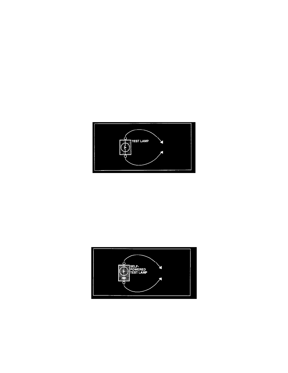
VOLTMETER AND TEST LAMP
Use a test lamp or a voltmeter on circuits without solid-state units and use a test lamp to check for voltage. A test lamp is made up of a 12-volt light bulb
with a pair of leads attached. After grounding one lead, touch the other lead to various points along the circuit where voltage should be present. When the
bulb goes on, there is voltage at the point being tested
CAUTION A number of circuits include solid-state modules, such as the Engine Control Module(ECM), used with fuel injection.
Voltage in these circuits should be tested only with a 10-megaohm or higher impedance DVOM. Never use a test lamp on circuits that contain solid state
modules. Damage to the modules may result.
A voltmeter can be used in place of a test lamp. While a test lamp shows whether the voltage is present or not, a voltmeter indicates how much voltage is
present.
SELF-POWERED TEST LAMP AND OHMMETER
Use a self-powered test lamp or an ohmmeter to check for continuity. The ohmmeter shows how much resistance there is between two points along a
circuit. Low resistance means good continuity.
CAUTION Never use a self-powered test lamp on circuits that contain solid state modules. Damage to these modules may result.
An ohmmeter can be used in place of a self-powered test lamp.
The ohmmeter shows how much resistance there is between two points along a circuit. Low resistance means good continuity.
Circuits which include any solid-state devices should be tested only with a 10-megaohm or higher impedance digital multimeter. When measuring
resistance with a digital multimeter, the component being tested should be isolated from the circuit (component disconnected, power OFF). Otherwise,
there may be incorrect readings. Diodes and solid-state devices in a circuit can make an ohmmeter give a false reading
To find out if a component is affecting a measurement, take one reading, reverse the leads and take a second reading.
If different the solid-state device is affecting the measurement.
JUMPER WIRE WITH FUSE
Use a jumper wire with a fuse to by-pass an open circuit.