
Rondo L4-2.4L (2007)
Relay Box: Testing and Inspection
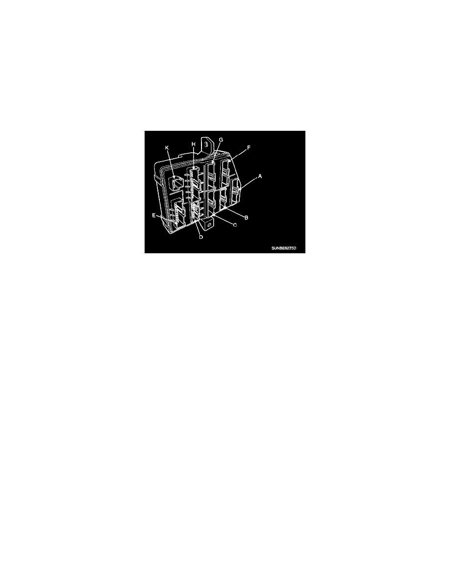
Relay Box (Passenger Compartment)
RELAY BOX (PASSENGER COMPARTMENT)
INSPECTION
FUSE
1. Be sure there is no play in the fuse holders, and that the fuses are held securely.
2. Are the fuse capacities for each circuit correct?
3. Are there any blown fuses?
If a fuse is to be replaced, be sure to use a new fuse of the same capacity. Always determine why the fuse blew first and completely eliminate the
problem before installing a new fuse.
PASSENGER COMPARTMENT RELAY
POWER WINDOW
Check for continuity between the terminals.
1. There should be continuity between the No.1 terminal in the I/P-K and the No.9 or 10 terminal in the I/P-G when power and ground are connected
to the No.1 terminal in the I/P-K and the No.7 terminal in the I/P-D.
2. There should be no continuity between the No.1 terminal in the I/P-K and the No.9 or 10 terminal in the I/P-G when power and ground are
connected to the No.1 terminal in the I/P-K and the No.? terminal in the I/P-D.
TAIL GATE
Check for continuity between the terminals.
1. There should be continuity between the No.13 terminal in the I/P-H and the No.1 terminal in the I/P-F when power and ground are connected to
the No.13 terminal in the I/P-H and the No.17 terminal in the I/P-D.
2. There should be no continuity between the No.13 terminal in the I/P-H and the No.1 terminal in the I/P-F when power and ground are connected to
the No.13 terminal in the I/P-H and the No.17 terminal in the I/P-D.
DOOR LOCK
Check for continuity between the terminals.
1. There should be continuity between the No.13 terminal in the I/P-H and the No.7 terminal in the I/P-G or No.12 terminal in the I/P-D when power
and ground are connected to the No.13 terminal in the I/P-H and the No.15 terminal in the I/P-D.
2. There should be no continuity between the No.13 terminal in the I/P-H and the No.7 terminal in the I/P-G or No.12 terminal in the I/P-D when
power and ground are connected to the No.13 terminal in the I/P-H and the No.15 terminal in the I/P-D.
DOOR UNLOCK
Check for continuity between the terminals.
1. There should be continuity between the No.2 terminal in the I/P-G and the No.2 or 13 terminal in the I/P-E when power and ground are connected
to the No.9 terminal in the I/P-D and the No.13 terminal in the I/P-E.
2. There should be no continuity between the No.2 terminal in the I/P-G and the No.2 or 13 terminal in the I/P-E when power and ground are
connected to the No.9 terminal in the I/P-D and the No.13 terminal in the I/P-E.
FOG LAMP