
Sorento 2WD V6-3.3L (2008)
9. Remove the side gear subassembly and repeat the tooth backlash procedure for the other gear pack on the opposite side of the case.
10. Remove the cross shaft, pinions and thrust washers and reinstall the first side gear subassembly and shim in the flange end of the case.
11. Install a pinion and thrust washer through each window so that the gear teeth mesh and so that the pinions are in line with each other. Rotate one
side gear so the pinions and thrust washers rotate at a position where they line up with the cross shaft holes in the case.
12. Install the pinion shaft, lock screw and lock washer. Tighten the lock screw to 30-40Nm (3.1 - 4.1 kg-m, 22-29lb-ft ) torque.
Disassembly
DISASSEMBLY
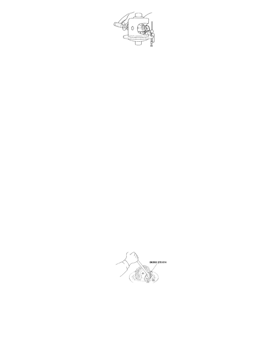
1. Remove the threaded lock screw and the cross shaft.
2. Without preload on the side gears they can be turned by hand. Rotate the side gears until the pinions are in the window area. Remove the pinions
and pinion thrust washers.
3. Remove the gear sub-assemblies (side gear, disc pack, ear guides and disc pack shims). Do not mix parts. Identify the parts so they can be
reassembled to the original location.
Inspection
INSPECTION
1. Check the side gears, pinions, pinion thrust washers, and cross shaft for wear or damage. If there is excessive wear, cracks, nicks, grooves or
galling replace the parts.
2. Inspect the carbon surfaces. After cleaning with a solvent, the carbon surface should appear like a course weave fabric with flat spots on the peaks
of the weave. If the surface is smooth, either from wear or from the weave filled with debris, replaces the entire disc pack.
3. Measure the thickness of the carbon friction discs. If any of the double sided discs are less than 2.56 mm (0.101in.) or the single sided disc is less
than 2.15mm (0.085 in.), replace the entire disc pack.
4. Inspect the splined friction discs If they have grooves or a mirror likes finishing, replacing the entire disc pack. Small scratches on a buff like
finish are okay.
Disassembly
DISASSEMBLY
1. SIDE BEARING NUT
NOTE:
Keep the right and left side bearing nuts separate so that they are not mixed during reassembly.
2. REMOVAL OF THE DIFFERENTIAL CASE ASSEMBLY
CAUTION:
-
Remove the differential case assembly slowly and carefully.
-
Be careful so that the side bearing outer race is not dropped.
-
Keep the right and left side bearing outer races separate so that they are not mixed during reassembly.