
Sorento 2WD V6-3.8L (2007)
SCHEMATIC DIAGRAM
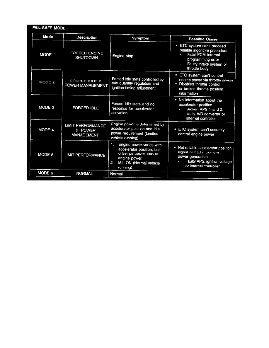
Fail-safe Mode
FAIL-SAFE MODE
COMPONENT INSPECTION
THROTTLE POSITION SENSOR (TPS)
1. Connect a scantool on the Data Link Connector (DLC).
2. Start engine and check output voltages of TPS 1 and 2 at C.T and W.O.T.
Specification: Refer to SPECIFICATION.
3. Turn ignition switch OFF and disconnect the scantool from the DLC.
4. Disconnect ETC module connector and measure resistance between ETC module terminals 4 and 8 (TPS 1).
5. Measure resistance between ETC module terminals 1 and 5 (TPS 2).
Specification: Refer to SPECIFICATION.
ETC MOTOR
6. Disconnect ETC module connector and measure resistance between ETC module terminals 2 and 3.
Specification: Refer to SPECIFICATION.
ETC SYSTEM INITIALIZATION
1. Erase the trouble codes on ECM
2. Turn the ignition key off and keep this condition until the main relay is turned off.(10 sec.)
3. Turn ignition key on more than 1 second to record the throttle motor position on the EEPROM