
Sorento 4WD V6-3.3L (2008)
CHECK SHORT CIRCUIT
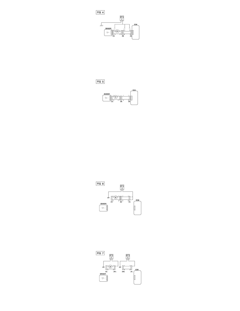
1. Test Method for Short to Ground Circuit
A. Continuity Check with Chassis Ground
If short to ground circuit occurs as shown in [FIG. 5], the broken point can be found by performing Step 2 (Continuity Check Method with Chassis
Ground) as shown below.
2. Continuity Check Method (with Chassis Ground)
NOTE:
Lightly shake the wire harness above and below, or from side to side when measuring the resistance.
Specification (Resistance)
1Ohms or less -> Short to Ground Circuit
1MOhms or Higher -> Normal Circuit
A. Disconnect connectors (A), (C) and measure for resistance between connector (A) and Chassis Ground as shown in [FIG. 6].
The measured resistance of line 1 and 2 in this example is below 1 Ohms and higher than 1MOhms respectively. Specifically the short to
ground circuit is line 1 (Line 2 is normal). To find exact broken point, check the sub line of line 1 as described in the following step.
B. Disconnect connector (B), and measure the resistance between connector (A) and chassis ground, and between (B1) and chassis ground as
shown in [FIG. 7].
The measured resistance between connector (B1) and chassis ground is 1Ohms or less. The short to ground circuit is between terminal 1 of
connector (C) and terminal 1 of connector (B1).