
Sorento 4WD V6-3.3L (2008)
2. Connector configuration (components)
-
The pages following the schematic diagrams contain data related to component connector configuration. Each page shows a terminal side view
of the connector. Refer to the "Connector View and Numbering Order" section in this document for information related to terminal numbering.
NOTE: a "*" symbol in place of a terminal number indicates an unused terminal (connector cavity will be empty).
3. Connector configurations (connection between harnesses)
-
The "Connector Configurations" section identifies connectors that are used to join harnesses together; junction connectors for common power
and ground wires are also identified in this section. Male and female connector views are shown applicable.
4. Component locations
-
Schematic diagrams include references to images found in the "Component Locations" section of this document. These images show
components and connectors in their installed location on the vehicle.
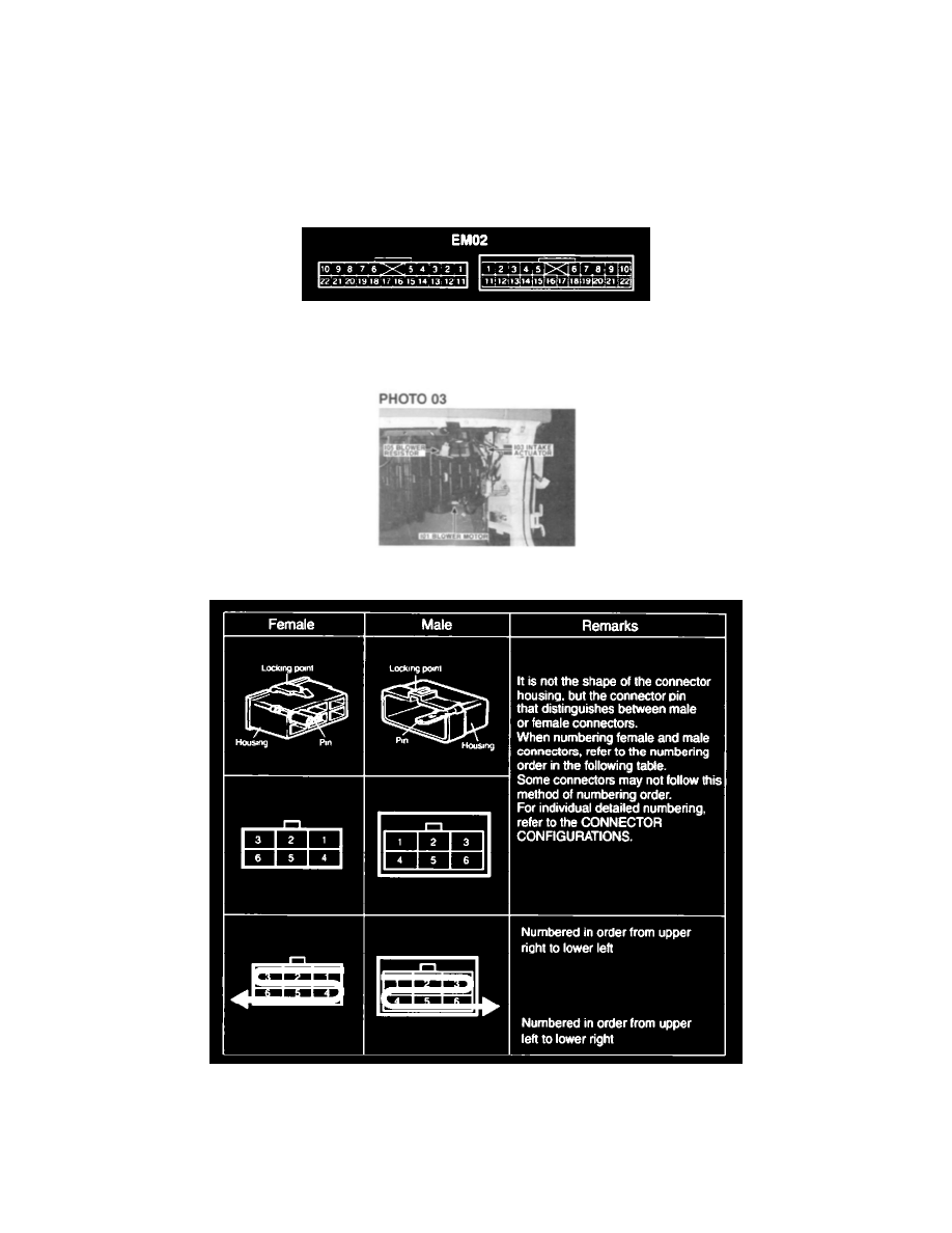
5. CONNECTOR VIEW AND NUMBERING ORDER
NOTE: UNLESS OTHERWISE STATED, ALL CONNECTOR VIEWS ARE FROM THE TERMINAL SIDE OF THE CONNECTOR.
6. WIRE COLOR ABBREVIATIONS
The following abbreviations are used to identify wire colors in the circuit schematics.