
Sportage 4WD L4-2.0L (2005)
Air Bag Control Module: Description and Operation
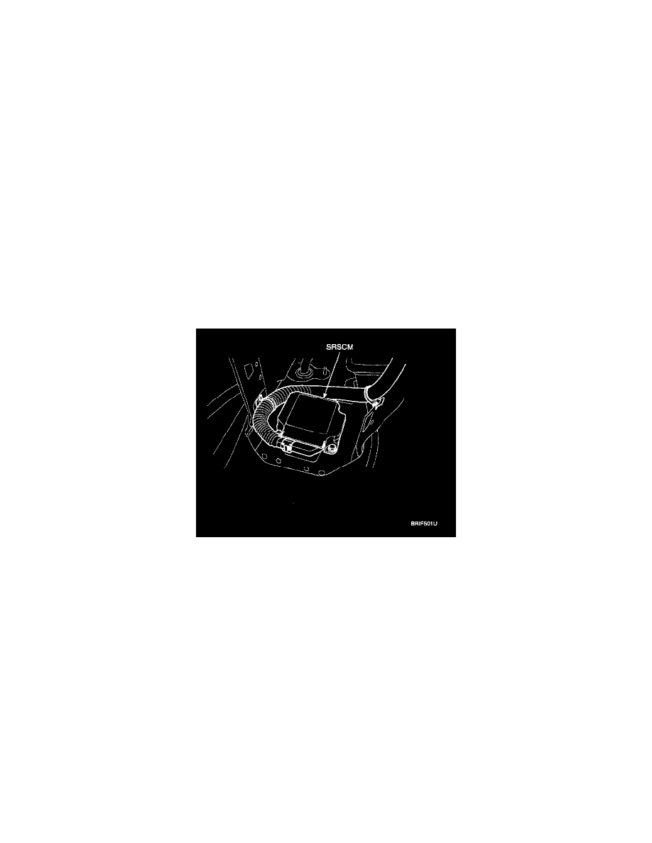
SRSCM (SRS CONTROL MODULE)
SRSCM will detect front impact with front impact sensor, and side impact with side impact sensor, and determine airbag module deployment.
1. DC/DC converter: DC/DC converter in power supply unit includes up/down transformer converter, and provide ignition voltage for 2 front airbag
ignition circuits and the internal operation voltage of the SRSCM. If the internal operation voltage is below critical value setting, it will perform
resetting.
2. Safety sensor: Safety sensor is located in airbag ignition circuit. Safety sensor will operate airbag circuit at any deployment condition and release
airbag circuit safely at normal driving condition. Safety sensor is a double contact electro-mechanical switch that will close detecting deceleration
above certain criteria.
3. Back up power supply: SRSCM has separate back up power supply, that will supply deployment energy instantly in low voltage condition or upon
power failure by front crash.
4. Self diagnosis: SRSCM will constantly monitor current SRS operation status and detect system failure while vehicle power supply is on, system
failure may be checked with trouble codes using scan tool. (Hi-Scan)
5. Airbag warning lamp on: Upon detecting error, the module will transmit signal to SRSCM indicator lamp located at cluster. MIL lamp will
indicate driver SRS error. Upon ignition key on, SRS lamp will turn on for about six seconds.
6. Trouble code registration: Upon error occurrence in system, SRSCM will store DTC corresponding to the error. DTC can be cleared only by
Hi-Scan. However, if an internal fault code is logged or if a crash is recorded the fault clearing should not happen.
7. Self diagnostic connector: Data stored in SRSCM memory will be output to Hi-Scan or other external output devices through connector located
below driver side crash pad.
8. Once airbag is deployed, SRSCM should not be used again but replaced.
9. SRSCM will determine whether passenger put on seat belt by the signal from built-in switch in seat belt buckle, and deploy front seat airbag at
each set crash speed.
10. Side airbag deployment will be determined by SRSCM that will detect satellite sensor impact signal upon side crash, irrespective to seat belt
condition.
SUPPLEMENTAL RESTRAINTS SYSTEM CONTROL MODULE(SRSCM)
SRS CONTROL MODULE
DESCRIPTION
The primary purpose of the advanced SRSCM (Supplemental Restraints System Control Module) is to discriminate between an event that warrants
restraint system deployment and an event that does not. The advanced SRSCM must decide if and when to deploy the restraint system pretensioners and
air-bags. After determining that pretensioners and/or airbag deployment is required, the advanced SRSCM must supply sufficient power to the
pretensioners and airbag igniters to initiate deployment. The advanced SRSCM determines that an impact may require deployment of the pretensioners
and airbags from data obtained from buckle switches, seat track position sensors, occupant classification system, front impact sensors and side impact
sensors in conjunction with a sating function. The advanced SRSCM will not be ready to detect a crash or to activate the restraint system devices until
the signals in the advanced SRSCM circuitry stabilize. It is possible that the advanced SRSCM could activate the safety restraint devices in
approximately 2 seconds but is guaranteed to fully function after prove-out is completed. The advanced SRSCM must perform a diagnostic routine and
light a system readiness indicator at key-on. The system must perform a continuous diagnostic routine and provide fault annunciation through a warning
lamp indicator in the event of fault detection. A serial diagnostic communication interface will be used to facilitate servicing of the advanced restraint
control system.