
Sportage 4WD 2Dr L4-2.0L (2002)
Alignment: Service and Repair
WARNING: PROVIDE SUFFICIENT SUPPORT FOR THE VEHICLE TO REDUCE THE POSSIBILITY OF THE VEHICLE FALLING,
CAUSING PERSONAL INJURY OR DEATH.
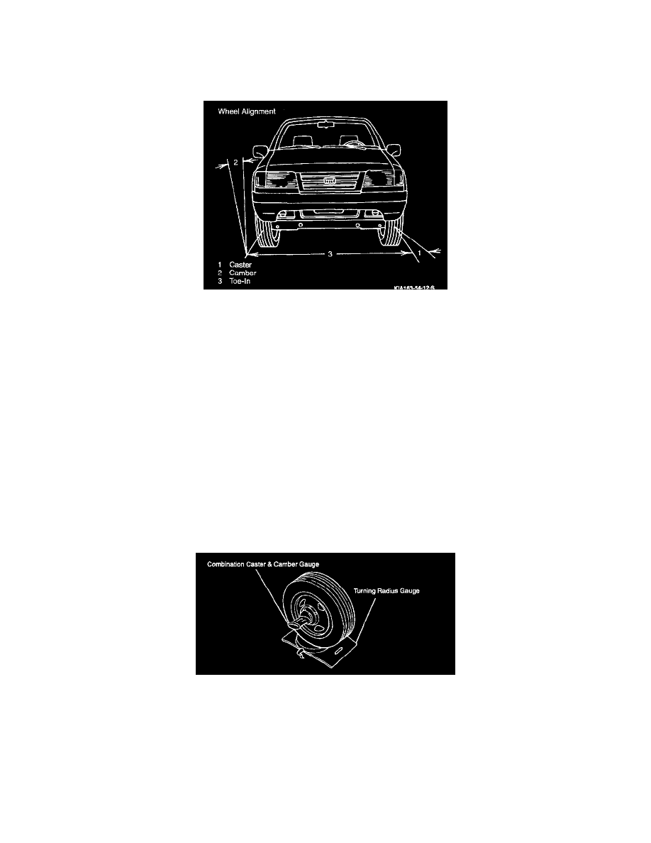
Front Wheel Alignment
Wheel alignment refers to the angular relationship between the wheels, control arms, suspension and the ground. It deals with tire camber, caster,
toe-in and wheel balancing. Proper wheel alignment and wheel balance insures a safe, quiet ride with minimal tire wear. This information assumes that
all components are in good working condition. Performing this exercise may also detect any problem areas in the front suspension. It is advisable to
replace defective components before attempting a wheel alignment.
Inspection
1. Inspect tires for proper balance and inflation. Balance tires and set to the recommended pressure if necessary.
2. Inspect front wheel bearing play and reduce the bearing play; replace any defective bearings.
3. Inspect for any excessive looseness of the ball joints and steering center link.
4. Place the vehicle on level ground and confirm that there are no passengers or luggage on board.
5. Push down on the front of the vehicle to determine the correct operation of the shock absorbers.
Camber
Camber is the tilting of the front wheels from the vertical when viewed from the front of the vehicle. When the wheels tilt outward at the top, the
camber is "positive" (+). When the wheels tilt inward at the top, the camber is "negative" (-). The amount of tilt is measured in degrees from the
vertical. Camber setting will influence directional control and tire wear.
Inspection
1. Position the vehicle so that the front wheel is on the turning-radius gauge.
2. Remove the front wheel hub.
3. Attach the standard camber gauge to the hub and measure the camber.
Camber:
0.44° ±0.75° (No Passenger Load)
0° ±0.75° (2 Passenger Load)
Adjustment
1. Turn the front spindle clockwise so that the number "2" mark is aligned with the vertical line on the spindle bracket.