
Sportage 4WD 4Dr L4-2.0L (2000)
Alarm Module: Diagram Information and Instructions
Circuit Schematics
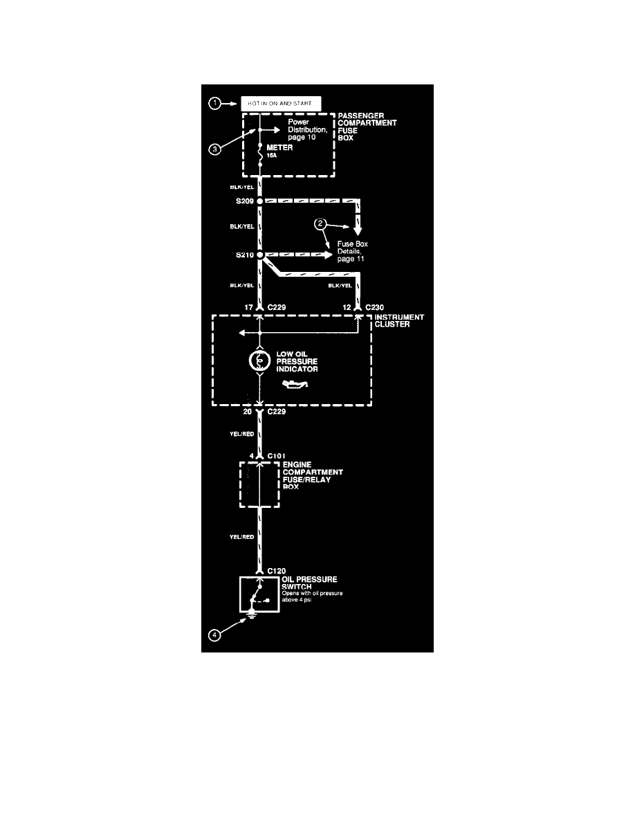
Each schematic is arranged so current flows from power at the top of the image, to ground at the bottom of the image. The "HOT" labels (1) at the top of
a fuse tell you when the ignition switch supplies power to that fuse.
Each circuit is shown completely and independently in one schematic. Other circuits getting their power from the same point, grounding at the same
point, are not shown. However, if other circuits actually share some wires, those wires will be shown also.
Wires that connect to another circuit are shown with an arrowhead pointing in the direction of current flow. Next to the arrowhead (2) is the name of the
circuit or component that shares that wiring. You can quickly check shared wiring by checking the operation of components.
"See Power Distribution" (3) means there are more connections here to other circuits shown in the Power Distribution schematic.