
300Tdi Defender
STEERING
1
DESCRIPTION AND OPERATION
DESCRIPTION
The steering system incorporates a compression joint
in the lower shaft and is designed to collapse on
impact. The mis-alignment of the upper steering
column with the steering box and the inclusion of two
universal joints, is also designed to prevent the
column moving toward the driver under frontal impact.
The steering box is located behind the first chassis
cross member and is connected to the road wheel
swivel housing by a drag link and track rod. A
hydraulic damper absorbs shocks in the steering,
caused by road wheel deflections when operating on
rough terrain.
Power steering system
The power steering system comprises a hydraulic
pump which is belt driven from the engine and
supplied with fluid from a reservoir that also acts as a
cooler.
The steering box houses a self neutralizing rotary
valve which is part of the worm/valve assy and an
hydraulic piston/rack to assist the mechanical
operation. The rotary valve which is operated by
movement of the steering wheel, directs fluid pressure
to the appropriate side of the hydraulic piston/rack to
provide assistance.
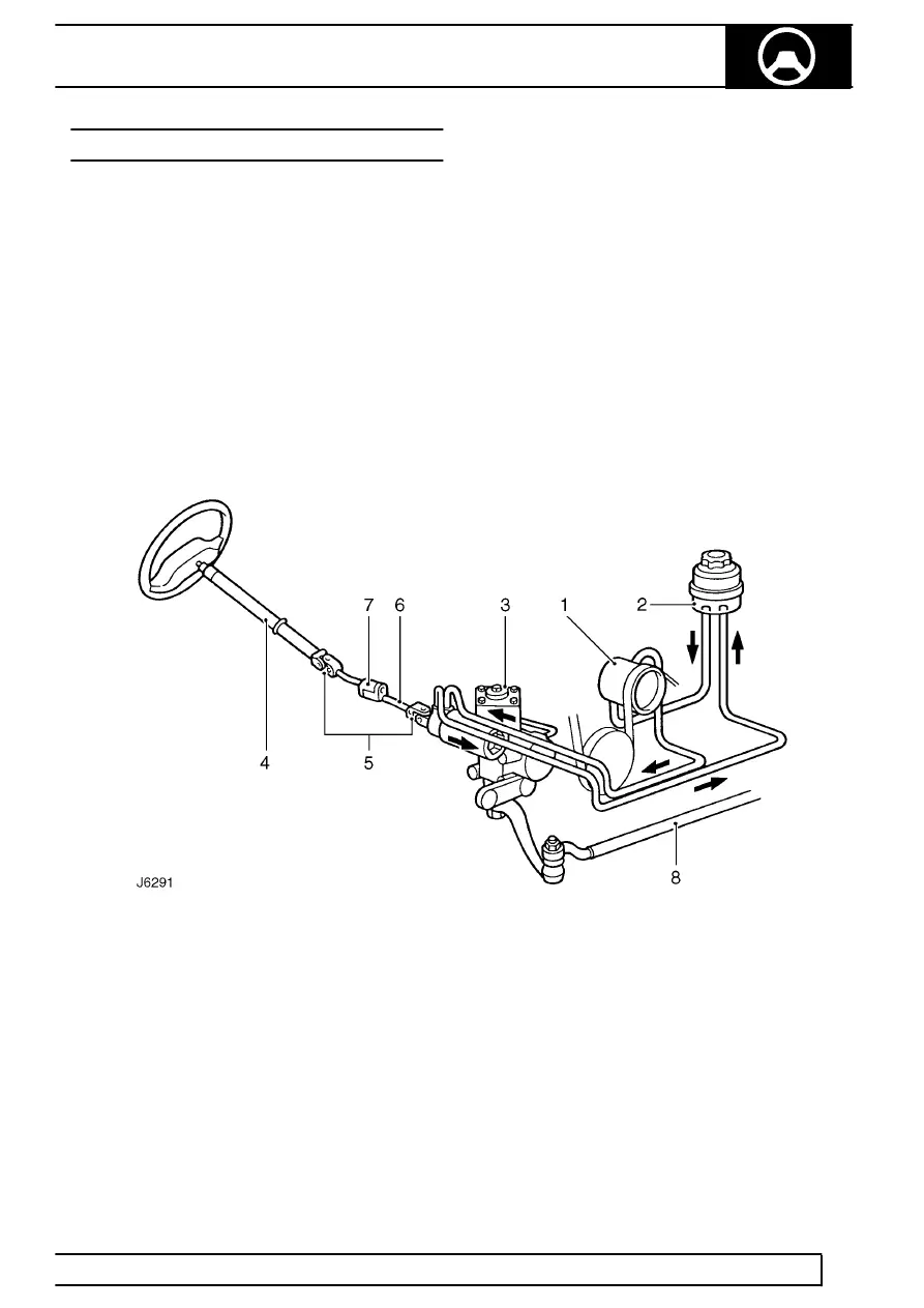
Power steering system
1. Hydraulic pump
2. Fluid reservoir
3. Steering box
4. Upper column
5. Universal joints
6. Lower shaft
7. Compression joint
8. Drag link