
TD5 Defender
ENGINE
7
OVERHAUL
CYLINDER HEAD GASKET SELECTION
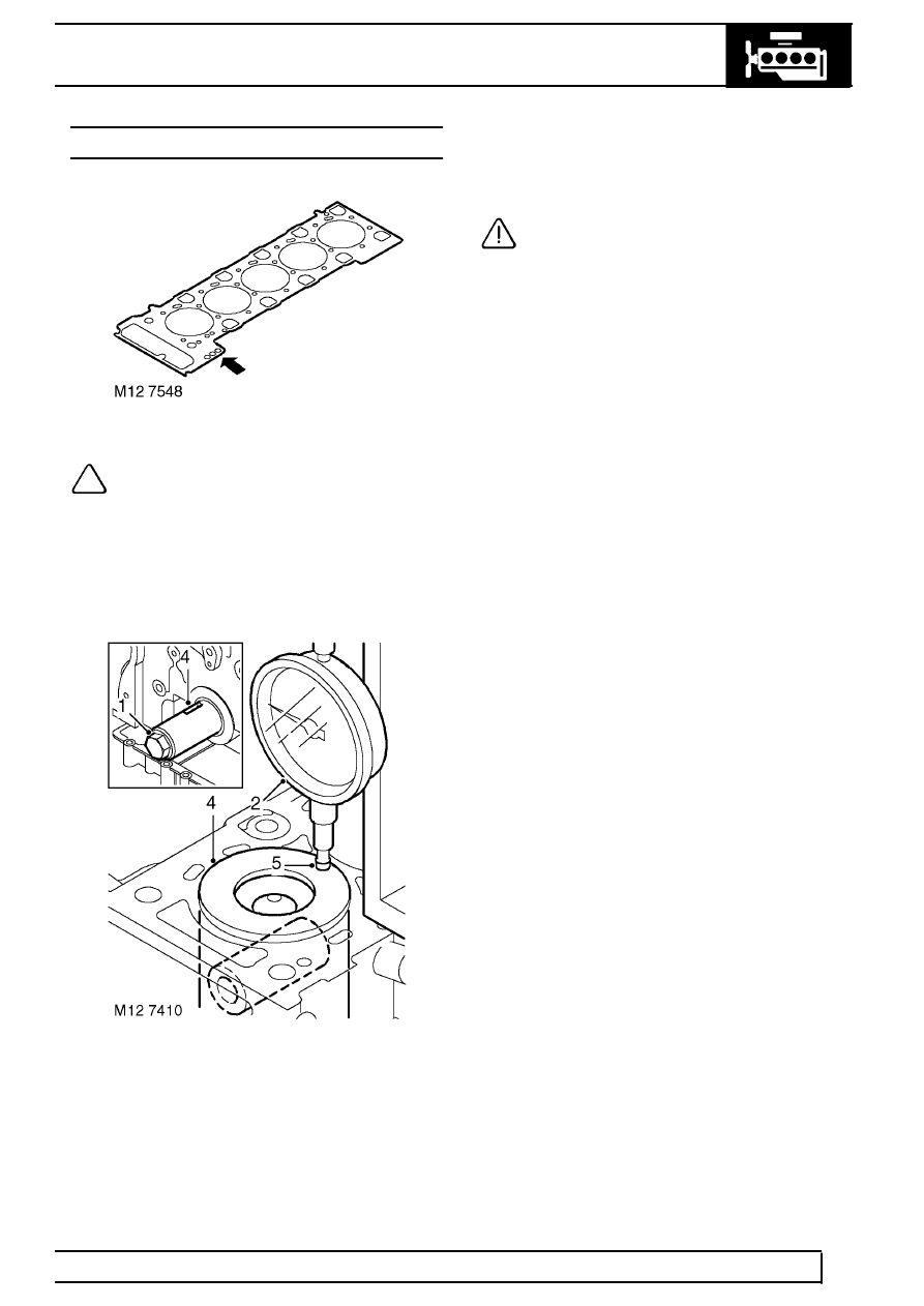
NOTE: There are three thicknesses of
cylinder head gasket available and in order
that the correct gasket is fitted, it will be
necessary to determine the stand proud
(protrusion) of each piston above the top face of
the cylinder block. Gaskets have either 1, 2 or 3
identification holes and the following procedures
must be followed in order that the correct gasket
is selected.
1. Temporarily fit and lightly tighten a new
crankshaft pulley bolt.
2. Assemble a magnetic base DTI to cylinder block
top face adjacent to No. 1 cylinder bore.
3. Position stylus to cylinder block top face and
zero gauge.
4. Using crankshaft pulley bolt, rotate crankshaft in
a clockwise direction until No.1 piston is at TDC -
Woodruff key slot in crankshaft is at 12 o’clock.
5. Position stylus of DTI at edge of piston and
directly over gudgeon pin axis.
6. Measure and record No.1 piston protrusion.
CAUTION: Measurement must be taken at
front and rear of piston.
7. Establish average of the 2 readings taken.
8. Repeat above procedures for remaining pistons.
9. From readings obtained, determine HIGHEST
piston protrusion figure and select the
appropriate cylinder head gasket:
Piston protrusion = 0.351 to 0.50 mm (0.014 to
0.02 in) - Select the 2 hole gasket.
Piston protrusion = 0.501 to 0.57 mm (0.021 to
0.022 in) - Select the 1 hole gasket.
Piston protrusion = 0.571 to 0.65 mm (0.022 to
0.025 in) - Select the 3 hole gasket.
10. Remove DTI.
11. Fit cylinder head gasket. See this Section.