
Discovery II
AIR CONDITIONING
82-8
DESCRIPTION AND OPERATION
Thermostatic expansion valve
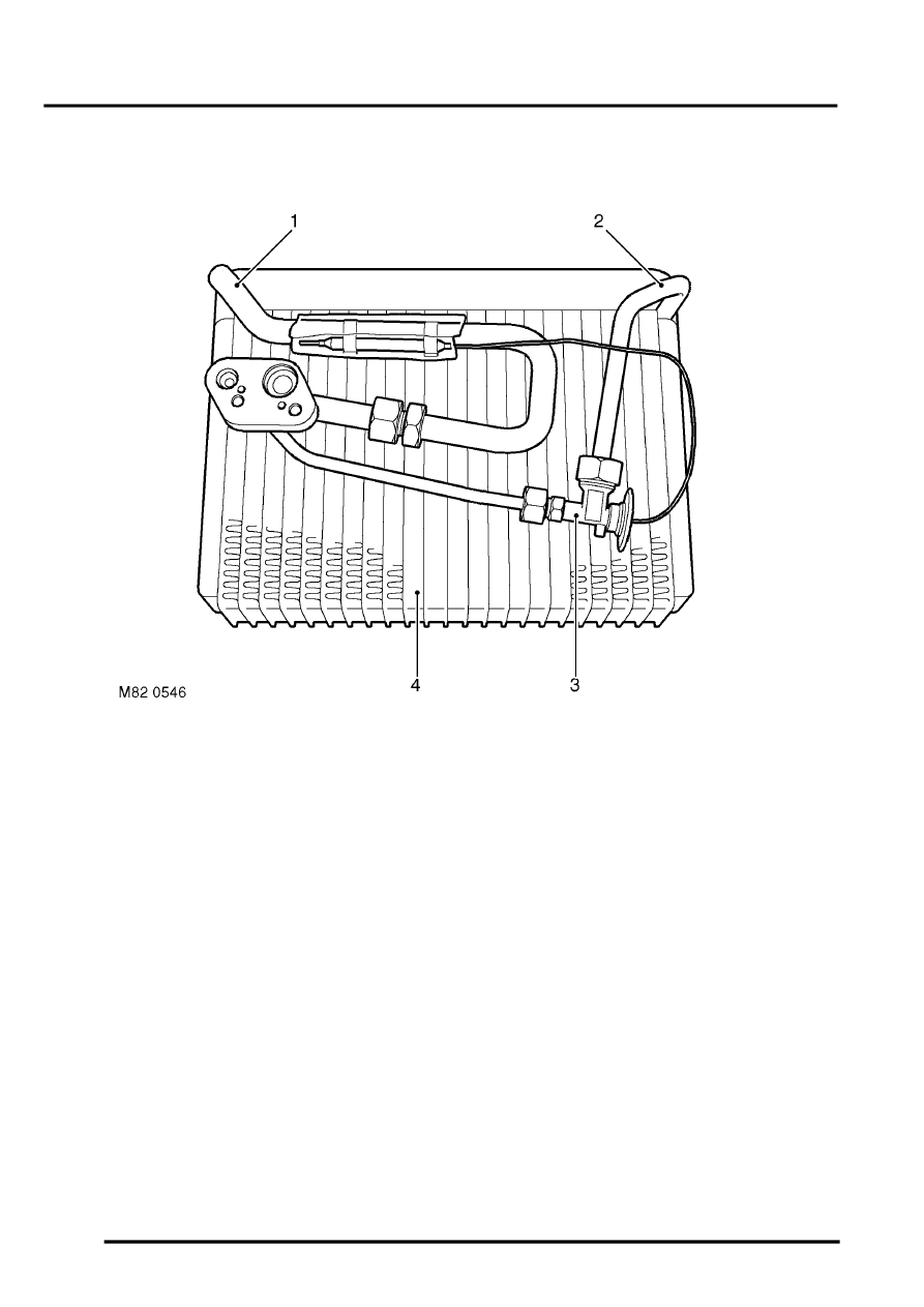
Thermostatic expansion valve and evaporator
1 Refrigerant outlet
2 Refrigerant inlet
3 Thermostatic expansion valve
4 Evaporator
The thermostatic expansion valve meters the flow of refrigerant into the evaporator to match the refrigerant flow with
the heat load of the air passing through the evaporator matrix.
The thermostatic expansion valve is installed in the heater assembly, in the refrigerant inlet line to the evaporator.
Liquid refrigerant flows through the valve to the evaporator. The restriction across the valve reduces the pressure and
temperature of the refrigerant and changes it to a fine spray, which improves the evaporation process. Valve opening
is controlled by the pressure in a capillary tube containing a temperature sensitive fluid. One end of the capillary tube
is connected to a diaphragm housing on the thermostatic expansion valve, the other end of the capillary tube is sealed
and attached to the refrigerant outlet line of the evaporator. As the temperature of the refrigerant leaving the
evaporator changes, a corresponding change of capillary tube pressure and valve opening are produced. The warmer
the refrigerant leaving the evaporator becomes, the greater the volume of refrigerant allowed through the valve.
Evaporator
The evaporator is installed in the air inlet of the heater assembly and absorbs heat from the exterior or recirculated
inlet air. Low pressure, low temperature refrigerant changes from liquid to vapour in the evaporator, absorbing large
quantities of heat as it changes state.
Refrigerant lines
To maintain similar flow velocities around the system, the diameter of the refrigerant lines varies to suit the two
pressure/temperature regimes. The larger diameters are installed in the low pressure/temperature regime and the
smaller diameters are installed in the high pressure/temperature regime. Low and high pressure charging connections
are incorporated into the refrigerant lines for system servicing. Where rear AC is installed, connections for the rear
refrigerant lines are incorporated next to the charging connections.