
Discovery II
ALARM SYSTEM AND HORN
86-4-4
DESCRIPTION AND OPERATION
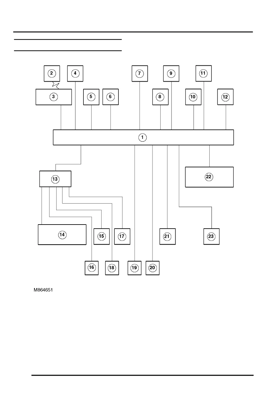
Alarm system block diagram
1 Body Control Unit (BCU)
2 Remote handset
3 Receiver
4 Fuel cut off switch
5 Ignition switch
6 Central door locking switch
7 Volumetric sensors
8 Bonnet activated alarm switch
9 Drivers door key lock/unlock switches
10 Door latch switches
11 Fuel flap release switch
12 Intelligent Driver Module (IDM)
13 Battery Backed Up Sounder (BBUS)
14 Alarm sounder
15 Vehicle horns
16 Direction indicators
17 Door lock actuators
18 Engine Control Module (ECM)
19 Starter motor