
Discovery II
EMISSION CONTROL - V8
17-2-20 DESCRIPTION AND OPERATION
For NAS vehicles with positive pressure, EVAP system leak detection capability, the atmosphere vent line from the
EVAP canister connects to a port on the fuel leak detection pump via a short, large bore hose which is secured to the
component ports by crimped metal clips at each end. A large bore plastic hose from the top of the leak detection pump
is routed to the RH side of the engine bay where it connects to an air filter canister. Under normal operating conditions
(when the fuel leak detection solenoid valve is not energised), the EVAP canister is able to take in clean air via the
air filter, through the pipework and past the open solenoid valve to allow normal purge operation to take place and
release any build up of EVAP system pressure to atmosphere.
The EVAP system pipes are clipped at various points along the pipe runs and tied together with tie straps at suitable
points along the runs.
The NAS and ROW EVAP canisters are of similar appearance, but use charcoal of different consistency. The ROW
vehicles use granular charcoal of 11 bwc (butane working capacity) and NAS vehicles use pelletised charcoal with a
higher absorption capacity of 15 bwc. All canisters are of rectangular shape and have capacities of 1.8 litres (3 1/8
imp. pts) with purge foam retention.
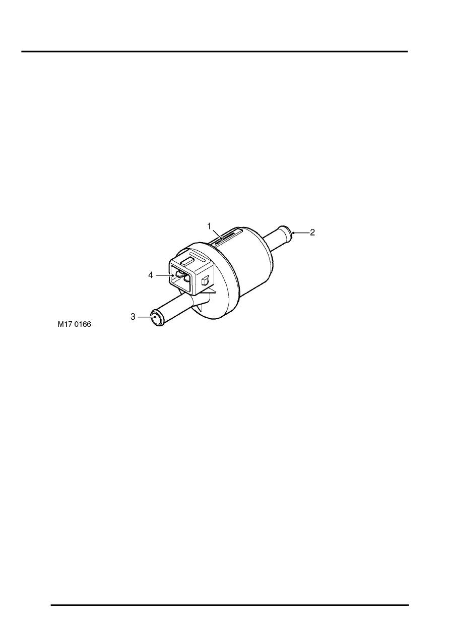
Purge Valve
1 Direction of flow indicator
2 Inlet port – from EVAP canister
3 Outlet port – to inlet manifold
4 Integral electrical connector
The EVAP canister purge valve is located in the engine bay at the LH side of the engine intake manifold. The valve
is held in position by a plastic clip which secures the inlet pipe of the purge valve to a bracket mounted at the rear of
the engine compartment. On vehicles with secondary air injection, the purge valve is fixed to a metal bracket together
with the SAI vacuum solenoid valve; the purge valve is fixed to the bracket by two plastic clips.
A nylon pipe connects the outlet of the purge valve to the stub pipe on the plenum chamber via a short rubber hose.
The connector to the plenum chamber is a quick-release type, plastic 90
°
female elbow; the connection is covered by
a rubber seal which is held in position on the port stub pipe.
A service port is connected in line between the EVAP canister and the inlet side of the purge valve and is rated at 1
psi maximum regulated pressure. The service port must be mounted horizontally and is located close to the bulkhead
at the rear of the engine bay. The service point is used by dealers for pressure testing using specialist nitrogen test
equipment for localising the source of small leaks.
The purge valve has a plastic housing, and a directional arrow is moulded onto the side of the casing to indicate the
direction of flow. The head of the arrow points to the outlet side of the valve which connects to the plenum chamber.
Purge valve operation is controlled by the engine control module (ECM). The purge valve has a two-pin electrical
connector which links to the ECM via the engine harness. Pin-1 of the connector is the power supply source from fuse
2 in the engine compartment fusebox, and pin-2 of the connector is the switched earth from the ECM (pulse width
modulated (PWM) signal) which is used to control the purge valve operation time. Note that the harness connector
for the purge valve is black, and must not be confused with the connector for the Secondary Air Injection
vacuum solenoid valve which is grey.
When the purge valve is earthed by the ECM, the valve opens to allow hydrocarbons stored in the EVAP canister to
be purged to the engine inlet manifold for combustion.