
Discovery II
EMISSION CONTROL - V8
17-2-24 DESCRIPTION AND OPERATION
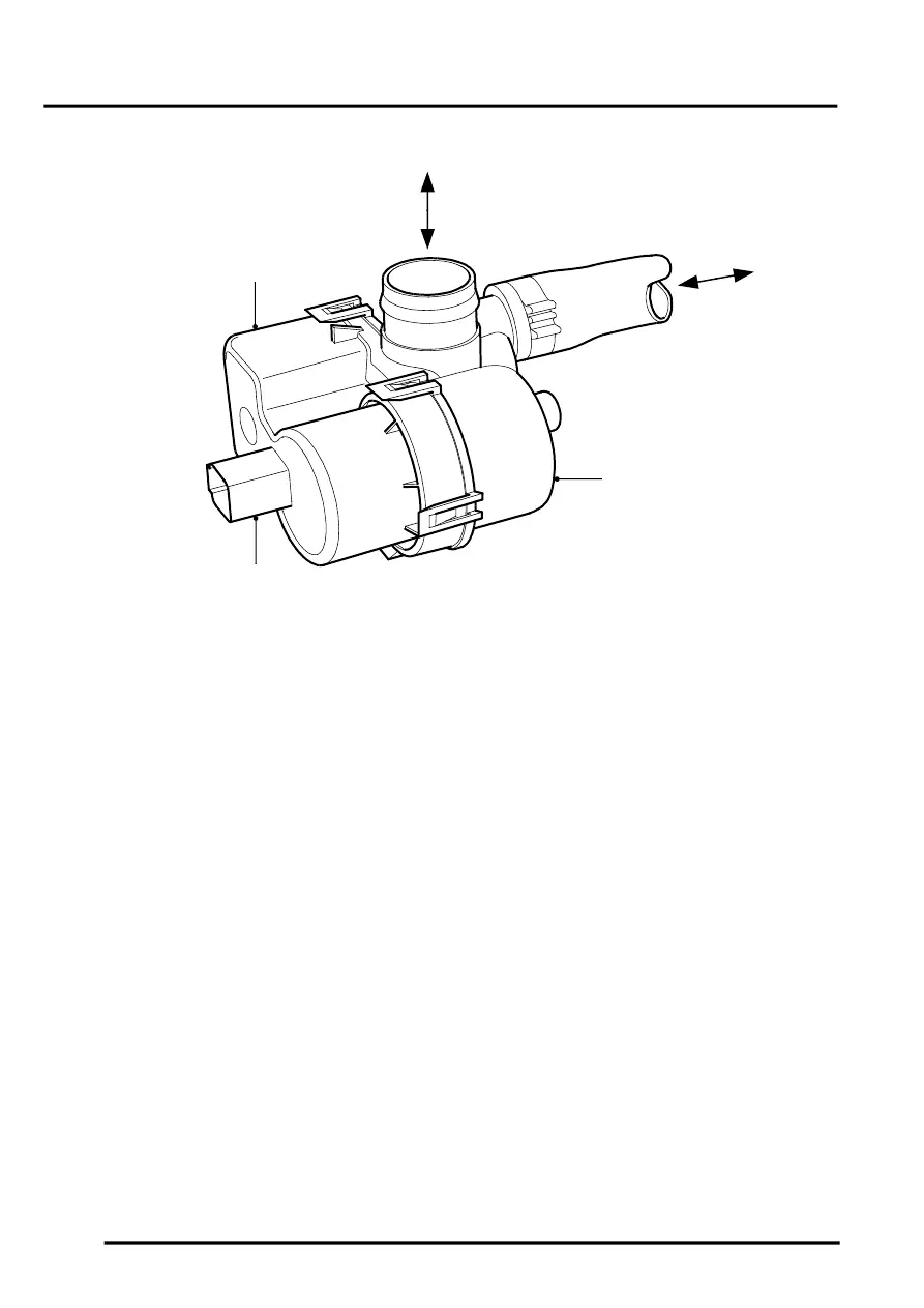
Leak Detection Pump (NAS vehicles with positive pressure EVAP system leakage test only)
1 Harness connector
2 Leak detection pump motor
3 Atmosphere connection to/from EVAP canister
4 Atmosphere connection to/from air filter
5 Leak detection pump solenoid valve
The fuel evaporation leak detection pump is mounted forward of the EVAP canister on a bracket fitted beneath the
vehicle on the RH side of the vehicle chassis. The leak detection pump is fixed to the bracket by three screws through
the bottom of the bracket.
A short hose connects between the atmosphere vent port of the EVAP canister and a port at the rear of the fuel
evaporation leak detection pump. The hose is secured to the ports at each end by crimped metal band clips.
An elbowed quick fit connector on the top of the fuel evaporation leak detection pump connects to atmosphere via a
large bore pipe. The pipe is routed along the underside of the vehicle chassis and up into the RH side of the engine
compartment where it connects to an air filter canister.
The leak detection pump incorporates a 3–pin electrical connector. Pin-1 is the earth switched supply to the ECM for
control of the pump solenoid valve. Pin-2 is the earth switched supply to the ECM for the operation of the pump motor.
Pin-3 is the power supply to the pump motor and solenoid valve and is switched on at system start up via the main
relay and fuse 2 in the engine compartment fusebox.
Under normal circumstances (i.e. when the leak detection pump is not operating and the solenoid is not energised),
the EVAP canister vent port is connected to atmosphere via the open solenoid valve.
The pump is operated at the end of a drive cycle when the vehicle is stationary and the ignition is switched off.
The leak detection pump module contains an integral air by-pass circuit with restrictor (reference-leak orifice) which
is used for providing a reference value for the leak detection test. The restrictor corresponds to an air leak equivalent
to 0.5 mm (0.02 in) diameter. With the solenoid valve open and the purge valve closed, the pump forces pressurised
air through the orifice while the current drawn by the leak detection pump motor is monitored to obtain the reference
value. The orifice must be kept free from contamination, otherwise the reference restriction may appear less than for
a 0.5 mm leak and consequently adversely affect the diagnostic results.
M17 0213
3
4
5
1
2