
Discovery II
EMISSION CONTROL - V8
DESCRIPTION AND OPERATION 17-2-25
During the leakage test, the solenoid valve is energised, closing the atmosphere vent line between the EVAP canister
and atmosphere and opening a path to the pressurised air supplied from the leak detection pump motor. Air is pumped
into the EVAP system, while the current drawn by the pump motor is monitored. The current drawn during the leakage
test is compared against the value obtained during the reference check, to determine if an EVAP system leak is
present.
The fuel leak detection pump is powered from a 12V supply and operates at a working pressure of 3 kPa.
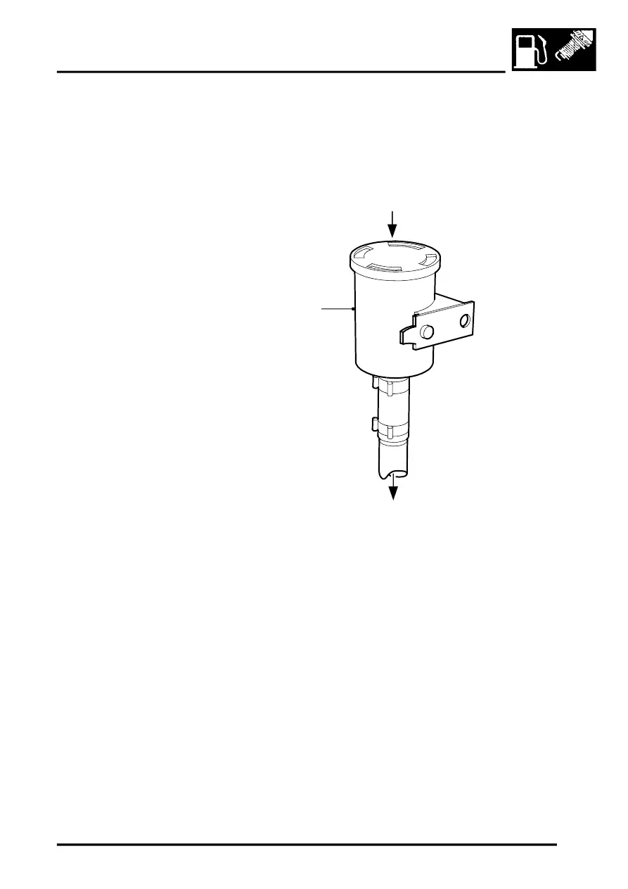
Air Filter – (NAS vehicles with positive pressure leak detection system only)
1 Air vents through canister lid
2 Air filter canister
3 To fuel leak detection pump
(EVAP canister atmosphere vent)
A paper element air filter (40
µ
m) is located in a plastic canister at the RH side of the engine compartment. The air
filter canister is fixed to the cruise control mounting bracket by a single nut and bolt. A large bore plastic pipe is
connected to a port at the base of the air filter canister and is secured to the port by a short nylon hose and two crimped
metal band clips.
The air filter is used to prevent particulate contaminants down to 40
µ
m from entering the fuel leak detection pump.
A press-fit lid on top of the canister contains slots to allow the passage of air into and out of the EVAP system.
The bottom end of the paper element is sealed to the canister and is non-serviceable (i.e fit for life). If necessary, the
canister and paper filter must be replaced as a single, complete assembly.
M17 0203
2
1
3