
Discovery II
FUEL DELIVERY SYSTEM - V8
DESCRIPTION AND OPERATION
19-2-9
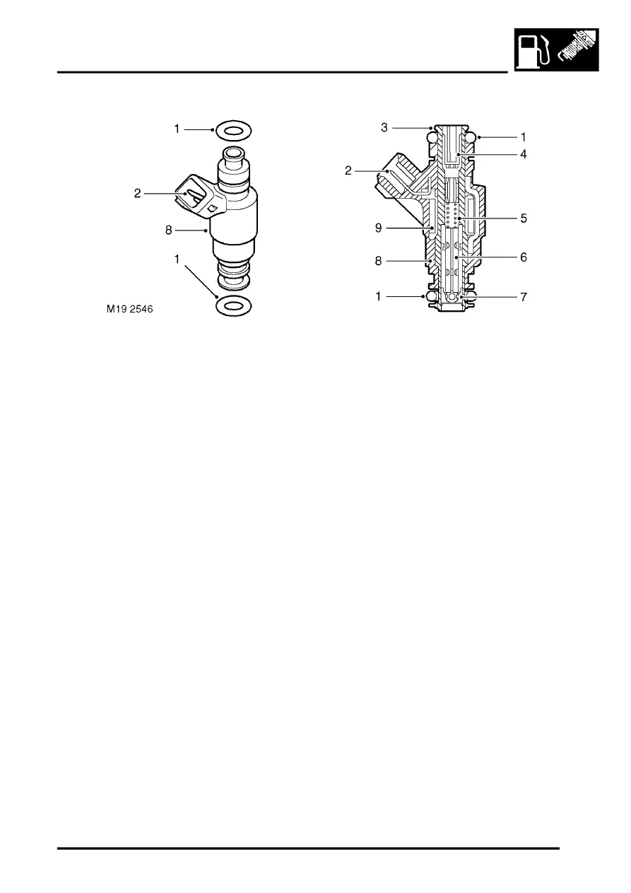
Injectors
1 'O' ring 2 off
2 Electrical connector
3 Steel housing
4 Filter strainer
5 Spring
6 Valve needle and armature
7 Valve seat/spray orifice
8 Plastic housing
9 Solenoid winding
An injector for each cylinder is mounted externally in the lower inlet manifold on the engine. The injector protrudes
into the inlet manifold tract, where it releases a controlled delivery of fuel into the manifold air inlet.
Each injector is sealed to the fuel rail and the inlet manifold with 'O' rings. Spring clips retain each injector to the fuel
rail and the attachment of the fuel rail clamps the injectors in the lower manifold.
The injector housing is manufactured from plastic which encapsulates a high-alloy steel housing. The steel housing
contains all components which come into contact with fuel. The plastic housing also provides the attachment for the
engine harness connector for the injector. A solenoid is located between the two housings and moves a valve needle
via an armature. The valve needle seats on a valve seat which incorporates a spray orifice plate. A filter strainer is
fitted at the connection with the fuel rail to remove any particulate matter from the fuel before it enters the injector.
When the ECM energises the solenoid, the armature moves lifting the valve needle off its seat. This allows
pressurised fuel from the fuel rail to pass through the injector housing and needle to the spray orifice. The spray orifice
controls the spray shape and fuel metering. When the solenoid is de-energised, the valve needle returns to the valve
seat, aided by a spring, closing off the injection of fuel into the inlet.
Each injector receives a battery supply voltage via a fuse in the engine compartment fusebox. The fuel delivery timing
is controlled by the ECM, which, at a precisely timed interval, provides a ground path for the injector. The completion
of the ground path operates the injector to allow fuel at pump pressure to be delivered from the fuel rail to the injector
nozzle. Each injector sprays a finely atomized spray of fuel into the inlet, where it is mixed with the intake air prior to
combustion.
ENGINE MANAGEMENT SYSTEM - V8, DESCRIPTION AND OPERATION, Description - engine
Faults for each injector are stored in the ECM and can be retrieved using TestBook. Each injector can be checked
across the two connector pins. For a correctly functioning injector a resistance of between 13.8 and 15.2 ohms at a
temperature of 20
°
C (65
°
F) should be read across the pins.