
L322 Range Rover System Description and Operation
AUTOMATIC TRANSMISSION – ZF 5HP24
DESCRIPTION AND OPERATION 44-2-33
Sensors
The 5HP24 transmission contains two speed sensors and a temperature sensor. The sensors are located inside the
transmission housing, with the speed sensors being the only serviceable items.
The sensors play an important part in the operation of the transmission and provide signal information to the EAT
ECU. This information is used by the ECU to control shift timing and fluid temperature to provide the optimum
operating condition for the transmission.
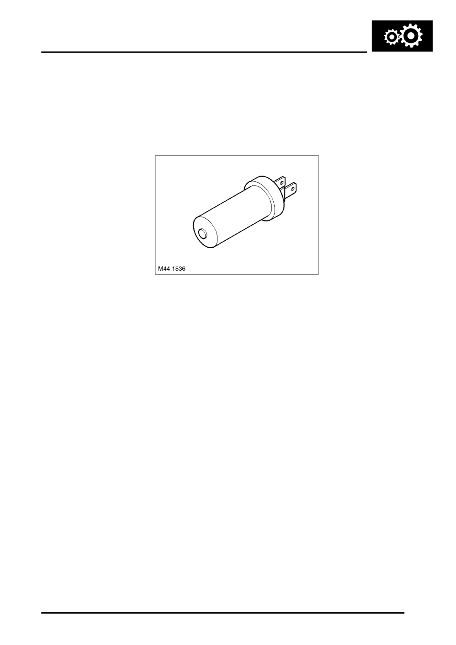
Speed Sensors
Two speed sensors are used in the 5HP24 transmission to monitor turbine speed and output shaft speed.
The turbine speed sensor is monitored by the EAT ECU to calculate the slip of the torque converter clutch and internal
clutch slip. This allows the EAT ECU to accurately control the slip timing during shifts and adjust clutch application or
release pressure for overlap shift control.
The output shaft speed is monitored by the EAT ECU and compared to engine speed signals received on the CAN
from the ECM. Using the comparison of the two signals the EAT ECU calculates the transmission slip ratio for
plausibility and maintain adaptive pressure control.
The turbine speed sensor is located in the main casing and secured with a screw. The sensor monitors turbine speed
from a toothed target wheel which on the outer diameter of clutch 'B' housing.
The output shaft speed sensor is located at the rear of the main casing and secured with a screw. The sensor monitors
the output shaft speed from a toothed target wheel which is an integral part of the park lock gear.
Both sensors are of the inductive type and are connected to the EAT ECU with two wires. The EAT ECU supplies a
positive DC supply and a signal return wire to monitors the sensor signals. Both wires are covered by a screen which
is connected to ground by the EAT ECU.
The sensor receives the DC supply from the EAT ECU. As the teeth of the target wheel pass the sensor tip, a change
in the magnetic field of the sensor occurs and generates an AC pulse in the sensor field winding. The pulse is passed
on the negative (ground) wire to the EAT ECU which calculates the rotational speed. The AC pulse generated is
proportional to the rotational speed of the target wheel. The EAT ECU measures the peak to peak outputs of the AC
waveform to calculate the rotational speed being measured.
The resistance of the coil winding in each sensor is between 285 and 365
Ω
at 20
°
C (68
°
F). Failure of either speed
sensor will cause the EAT ECU to store a related fault code.