
L322 Range Rover System Description and Operation
BRAKES
DESCRIPTION AND OPERATION
70-21
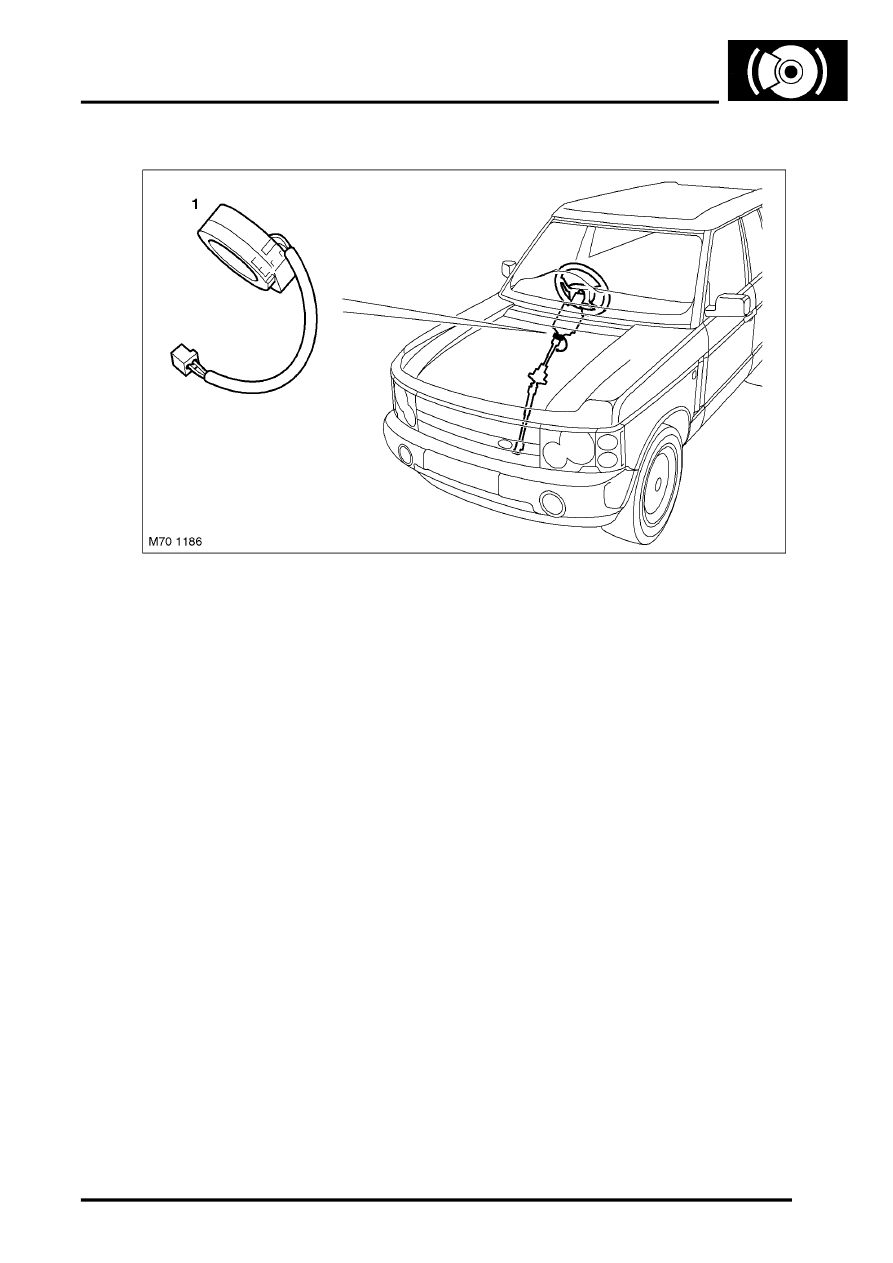
Steering Angle Sensor
1 Steering angle sensor
The Steering angle sensor is mounted at the bottom of the steering spindle at the base of the upper steering column
assembly.
The sensor is equipped with a processor and is directly linked to the CAN bus to communicate with the ABS ECU.
The sensor utilizes two potentiometers to determine the steering angle and the rate of steering. These are the raw
signals the steering angle microprocessor utilizes to create the steering angle signal for broadcast on the CAN bus.
The sensor requires calibration after repairs to the steering or suspension system. Once the calibration is completed
the sensor now also sends an identification number over the CAN bus to the ABS ECU. The ID provides confirmation
in the ABS ECU that the steering angle sensor is properly calibrated.
If the ID differs due to component replacement it will be necessary to enter the diagnostic system of the ABS system
to initiate the steering angle sensor calibration. DSC will not be available on the vehicle until the steering angle sensor
is calibrated. Once complete a new ID number is generated and the DSC ECU and Steering angle sensor are properly
mated.
The DSC logic checks the plausibility of the steering angle sensor against the other DSC inputs (front wheel speeds,
rotation and DSC sensor). If battery voltage is interrupted, the current steering wheel rotation is recalculated by the
ABS ECU evaluating the wheel speeds.
Replacement steering angle sensors must be coded when installed in the vehicle prior to the calibration procedure in
order to add the VIN to the angle sensor. Re-calibration is carried out by turning the steering lock to lock with the
engine running while stationary.
Brake Fluid Level Warning Switch
A fluid level switch is incorporated into the reservoir cap.
l
With sufficient fluid level the reed contact is closed
l
When level drops below allowable limits, switch opens.
Since the normal position is closed, this circuit is monitored for shorts to + and ground.
The ABS ECU monitors the fluid level and issues a low fluid level message on the CAN.