
L322 Range Rover System Description and Operation
DRIVE AND PROPELLER SHAFTS
DESCRIPTION AND OPERATION
47-5
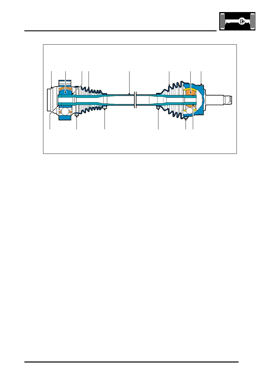
Rear Drive Shaft – Sectional View
1 End cap
2 Inner CV joint
3 Circlip
4 Gaiter
5 Tube
6 Outer CV joint
7 ABS Sensor target ring
8 Snap ring
9 Clamp
10 Circlip.
The CV joints used on the rear drive shafts are of the Birfield design. Refer to the Front Drive Shafts for a description
of the CV joints.
The outer CV joint is retained on the tube by an internal snap ring. The CV joint can be removed by a sharp tap with
a soft mallet on the CV joint housing which releases the snap ring from the groove. The inner CV joint is retained on
the shaft by two circlips. This CV joint is different in design to the outer CV joint but the operating principle is the same.
An end cap is pressed over the inner end of the CV joint to prevent the ingress of dirt and moisture. Both CV joints
are fitted with gaiters which are secured with metal clamps.
7
M47 0441
9
8
9
9
9
4
2
3
1
5
6
4
10