
L322 Range Rover System Description and Operation
ENTERTAINMENT AND INFORMATION SYSTEMS
86-8-60 DESCRIPTION AND OPERATION
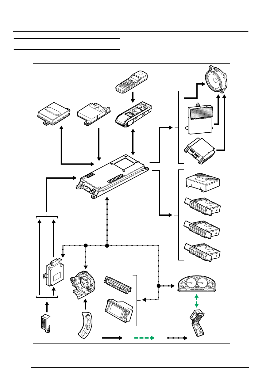
Telephone System Control Diagram
A = Hardwired connection; C = DS2 diagnostic bus; K = I bus
M86 5844
A
20
12
18
19
16
17
5
6
7
8
9
15
14
1
2
3
13
4
10
11
K
C