
L322 Range Rover System Description and Operation
STEERING
57-16
DESCRIPTION AND OPERATION
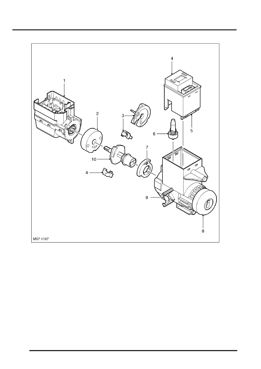
Ignition Switch and Locking Mechanism
1 Ignition switch contacts housing
2 Spacer
3 Key interlock mechanism
4 Ignition switch lock solenoid actuator
5 Hall sensor pick-up
6 Locking pin
7 Hall sensor target
8 Ignition key lock barrel
9 Key interlock cable connection point
10 Drive shaft and ignition switch lock cam
The ignition switch assembly also has a locking mechanism which works in conjunction with the immobilisation ECU
and the steering lock ECU. The ignition switch mechanism comprises an ignition switch lock solenoid actuator which
prevents the ignition switch being rotated unless the key has been recognised by the immobilisation ECU. A Hall
sensor is located in the ignition switch body and senses the rotation of the ignition switch. This signal is transmitted
on the K bus and is used by the steering lock ECU to confirm the key status with the immobilisation ECU. Refer to
Operation later in this section for functional description.