
L322 Range Rover System Description and Operation
SUSPENSION
60-2
DESCRIPTION AND OPERATION
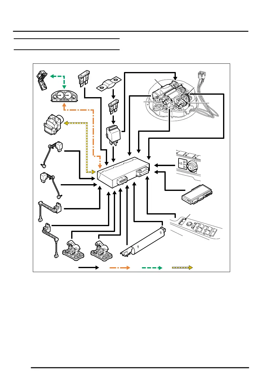
Suspension Control Diagram
A = Hardwired connections; B = K bus; C = Diagnostic DS2 bus; D = CAN bus
1 Fuse 15A – Permanent feed
2 Fusible link 100A
3 Fuse 50A
4 Air suspension relay
5 Compressor and motor
6 Temperature sensor
7 HP exhaust valve
8 Exhaust valve
9 Control switch
10 Body control Unit (BCU)
11 Air suspension ECU
12 Driver door module (Access mode switch)
13 Reservoir pressure sensor
14 Valve block
15 Front cross link valve
16 Rear cross link valve
17 LH rear height sensor
18 RH rear height sensor
19 LH front height sensor
20 RH front height sensor
21 ABS ECU
22 Instrument pack
23 Diagnostic socket
M60 0820A
1
A
2
3
4
9
10
11
12
13
14
15
16
17
18
19
20
8
5
7
6
C
21
23
B
D
22