
LR3/Disco 3
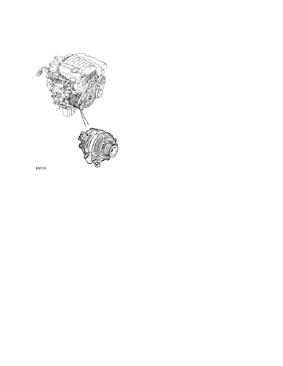
Generator
The generator is located at the front RH side of the engine, in front of the RH cylinder head. The generator has an output
of 85/150 Amps and is manufactured by Denso. A six-ribbed polyvee belt drives the generator pulley, which in turn is
driven from the engine crankshaft pulley.
The generator comprises a stator, a rotor, a rectifier pack and a regulator. There is a three-pin connector (C0053) on the
generator:
Pin 1 – Pulse Width Modulated (PWM) signal from the generator to the Engine Control Module (ECM) (generator
monitoring)
Pin 2 – PWM signal from the ECM to the generator (generator control)
Pin 3 – Voltage reference line to the battery via the Battery Junction Box (BJB).
The generator is connected to ground via its mountings.
The rotor comprises a field winding, wound around an iron core and mounted on a shaft. The iron core has extensions at
each end, which form North and South poles as current flows through the field winding. The rotor is located inside the
stator and is mounted on bearings for smooth running and to support the rotor due to the high side loading applied by the
drive belt tension.
The stator has three sets of coils made from copper wire. The three coil windings are connected in a 'star' connection,
where one end of the winding is connected to the other two windings. The output current is supplied from the opposite
end of each winding. Rotation of the rotor causes ac current to be produced in the coils.
The rectifier converts the ac current produced in the stator coils into dc (rectified) current required by the vehicle electrical
system. The rectifier comprises semi-conductor diodes mounted on a heatsink to dissipate heat. An equal number of the
diodes are on the negative and positive side, with an additional diode in the regulator to control the feedback through the
battery voltage signal line. The rectifier also prevents current flow from the battery to the generator when the output
voltage is less than the battery voltage.
The 'smart' regulator controls the output voltage from the generator to protect the battery; at low temperatures battery
charge acceptance is very poor so the voltage needs to be high to maximise any re-chargeability, but at high
temperatures the charge voltage must be restricted to prevent excessive gassing at the battery with consequent water
loss. The EMS, which controls the regulator, will calculate the voltage set point required for the ensuing conditions. The
'traditional' regulator controls voltage against generator temperature, which means the battery temperature will lag a long
Published : Apr 30, 2004