
Range Rover P38
EMISSION CONTROL
29
DESCRIPTION AND OPERATION
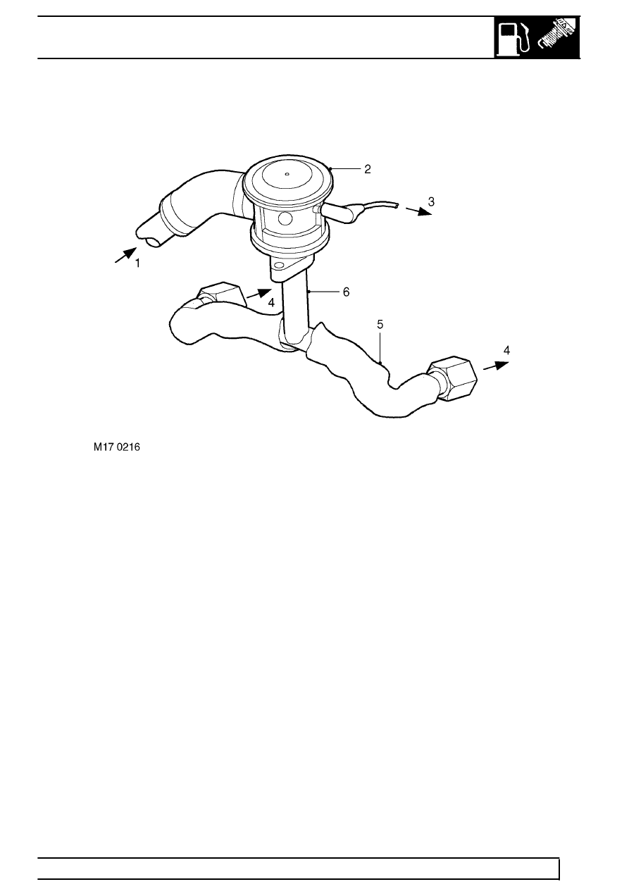
SAI control valves
1. Pressurised air from SAI pump
2. Vacuum operated SAI control valve
3. Vacuum hose from SAI vacuum solenoid valve
4. Pressurised air to exhaust manifold
5. Protective heat sleeving
6. Air delivery pipe to exhaust manifold
The SAI control valves are located on brackets at
each side of the engine.
The air injection supply pipes connect to a large bore
port on the side of each SAI control valve via a short
rubber connection hose. A small bore vacuum port is
located on each SAI control valve at the opposite side
to the air injection supply port. The vacuum supply to
each vacuum operated SAI control valve is through
small bore nylon hoses from the SAI vacuum solenoid
valve. An intermediate connector is included in the
vacuum supply line to split the vacuum applied to
each SAI control valve, so that both valves open and
close simultaneously.
When a vacuum is applied to the SAI control valves,
the valve opens to allow the pressurised air from the
SAI pump through to the exhaust manifolds. The
injection air is output from each SAI control valve
through a port in the bottom of each unit. A metal pipe
connects between the output port of each SAI control
valve and each exhaust manifold via an intermediate
T-piece. The T-piece splits the pressurised air
delivered to ports at the outer side of the two centre
exhaust ports on each cylinder head. The pipes
between the T-piece and the exhaust manifold are
enclosed in thermal sleeving to protect the
surrounding components from the very high heat of
the exhaust gas, particularly at high engine speeds
and loads.
When the SAI vacuum solenoid valve is de-energised,
the vacuum supply line opens to atmosphere, this
causes the vacuum operated valves to close
automatically and completely to prevent further air
injection.