
Range Rover P38
ZF AUTO
9
DESCRIPTION AND OPERATION
Torque converter housing
On 2.5 litre Diesel models a 260 mm (10.2 in)
diameter torque converter is used. On 4.0 and 4.6 litre
petrol models a 280 mm (11 in) diameter torque
converter is used. On 4.6 litre petrol models up to
99MY the torque converter is longer than the torque
converter used on 4.0 litre petrol models. From 99MY,
both the 4.0 and 4.6 litre petrol models use the shorter
torque converter previously used on up to 99MY 4.0
litre models.
The torque converter housing attaches the gearbox to
the engine and contains the torque converter. The
torque converter is connected to the engine drive
plate and transmits the drive from the engine to the
gearbox input shaft. When engaged, a hydraulic
lock-up clutch in the torque converter prevents
slippage, to give a direct drive from the engine to the
gearbox for improved efficiency.
Intermediate plate
The intermediate plate supports the gearbox input
shaft and provides the interface between the
transmission fluid pump and the lubrication circuit.
The pump attaches to the front of the intermediate
plate and is driven by an impeller in the torque
converter. The pump pressurises transmission fluid
drawn from the sump on the gearbox housing. The
pressurised fluid then circulates through the torque
converter and gearbox housing components for
cooling, lubrication and gear shift purposes. Ports
around the outer periphery of the intermediate plate
provide the inlet and outlet connections to the fluid
cooler and a pressure take-off point for servicing.
On ZF4HP24 gearboxes, the intermediate plate is
15 mm (0.6 in) thicker than fitted to the ZF4HP22
gearbox to accomodate a larger fluid pump unit. To
compensate for the increased length of the
intermediate plate, the rear extension housing is
15 mm (0.6 in) shorter than that fitted to the ZF4HP22
gearbox.
Gearbox housing
The gearbox housing contains two epicyclic gear sets
on input and output shafts. Hydraulic clutches on the
shafts control which elements of the gear sets are
engaged, and their direction of rotation, to produce the
P and N selections, four forward gear ratios and one
reverse gear ratio.
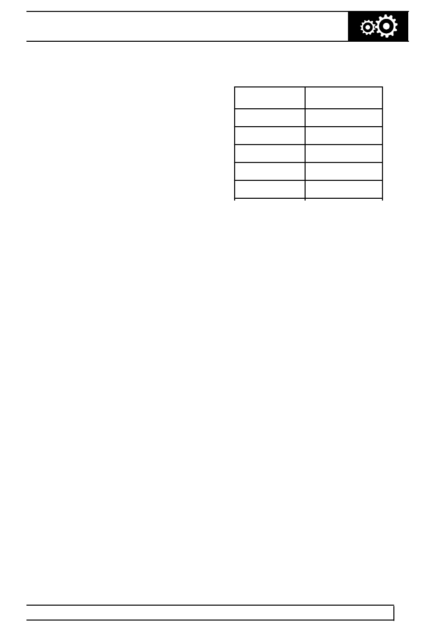
Gear ratios
Gear
Ratio
1st
2.480:1
2nd
1.480:1
3rd
1.000:1
4th
0.728:1
Reverse
2.086:1
The lock-up and brake clutches are operated by
pressurised transmission fluid from the valve block in
the sump. A manual valve and four solenoid valves,
also known as Motorised Valves (MV), control the
supply of pressurised transmission fluid from the valve
block:
•
The manual valve controls the fluid supply for P,
R, N and D selector positions. The four solenoid
valves operate accordingly to operate shift
control, lock-up and shift quality.
•
Solenoid valves MV 1 and MV 2 control the
supplies that operate the brake clutches for shift
control. They are also used to prevent accidental
engagement of reverse when moving forwards
and a forward gear when moving backwards.
•
Solenoid valve MV 3 controls the supply that
operates the lock-up clutch.
•
Solenoid valve MV 4 modulates the pressure of
the supplies to the brake clutches, to control shift
quality.
Operation of the manual valve is controlled by the
selector lever assembly. In the gearbox, a selector
shaft engages with the manual valve. The selector
shaft is connected to the selector lever assembly via
the selector cable and a selector lever on the left side
of the gearbox. The selector shaft also operates a
mechanism that locks the output shaft when P is
selected.
Operation of the solenoid valves is controlled by the
EAT ECU.