
Range Rover P38
64
REAR SUSPENSION
NEW RANGE ROVER
8
REPAIR
Do not carry out further dismantling if component
is removed for access only.
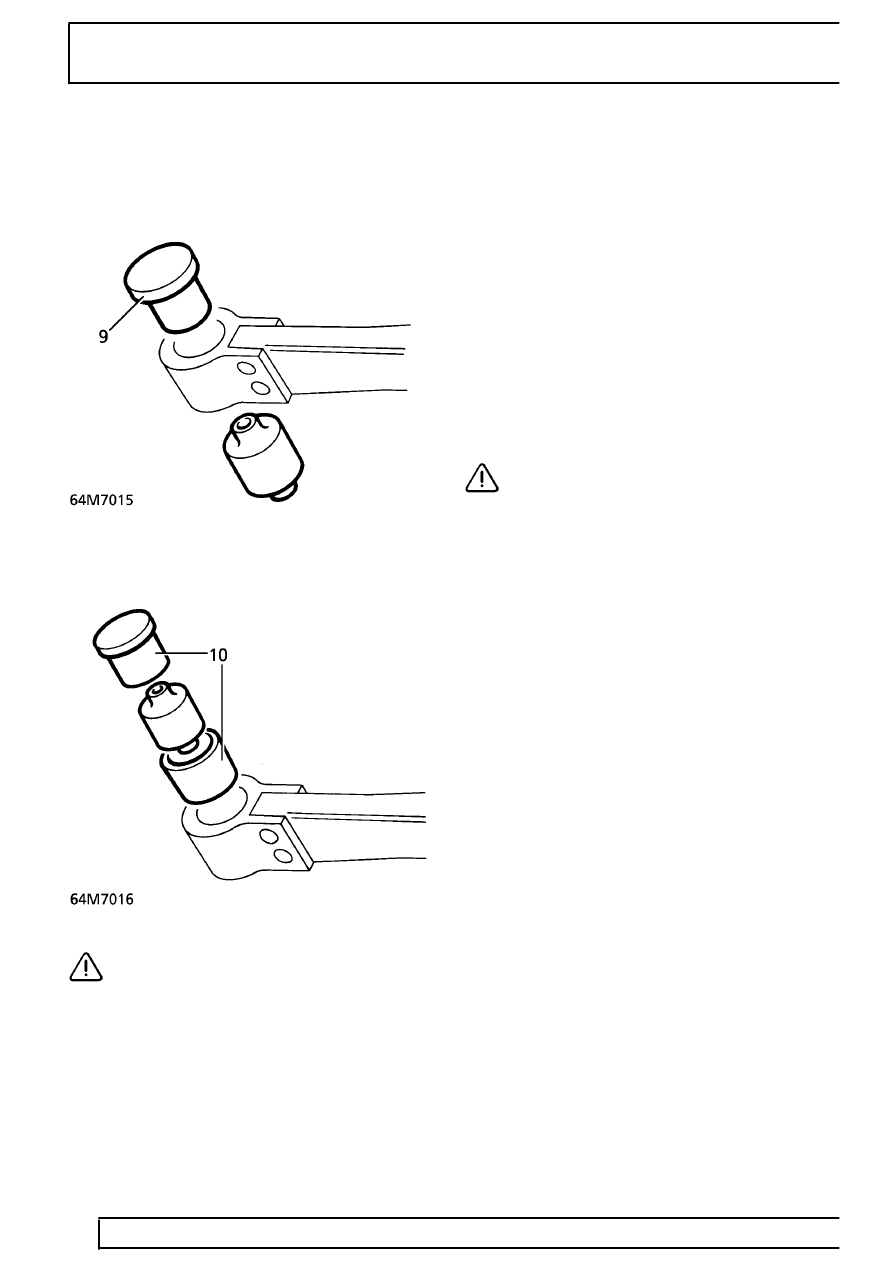
9. Using LRT-64-001, press bush from trailing arm.
10. Using LRT-64-001, press new bush into trailing
arm.
CAUTION: LRT-64-001 must be used to
compress the bush as it is pressed into
the arm. Damage to bush will result if
correct tool is not used.
Refit
11. Position trailing arm to vehicle and align to
chassis. Fit bolt but do not tighten at this stage.
12. Secure trailing arm to axle with nuts and bolts.
M16 with 8.8 strength grade - Tighten to
160 Nm. (118 lbf.ft),
M16 with 10.9 strength grade - Tighten to
240 Nm. (177 lbf.ft),
M12 - Tighten to
125 Nm. (92 lbf.ft)
13. Engage height sensor link into trailing arm
location.
14. Position upper mounting rubber. Engage shock
absorber to axle.
15. Position lower mounting rubber and washer.
Secure shock absorber to axle with nut. Tighten
to
45 Nm. (33 lbf.ft)
CAUTION: Washer must be fitted with
convex side towards rubber.
16. Remove safety stands. Lower vehicle.
17. Tighten bolt securing trailing arm to chassis.
Tighten to
160 Nm. (118 lbf.ft)
18. Lower ramp.