
R380 Manual Gearbox Overhaul: Gear Change/Selector Housings Maintenance
MANUAL GEARBOX
24
OVERHAUL
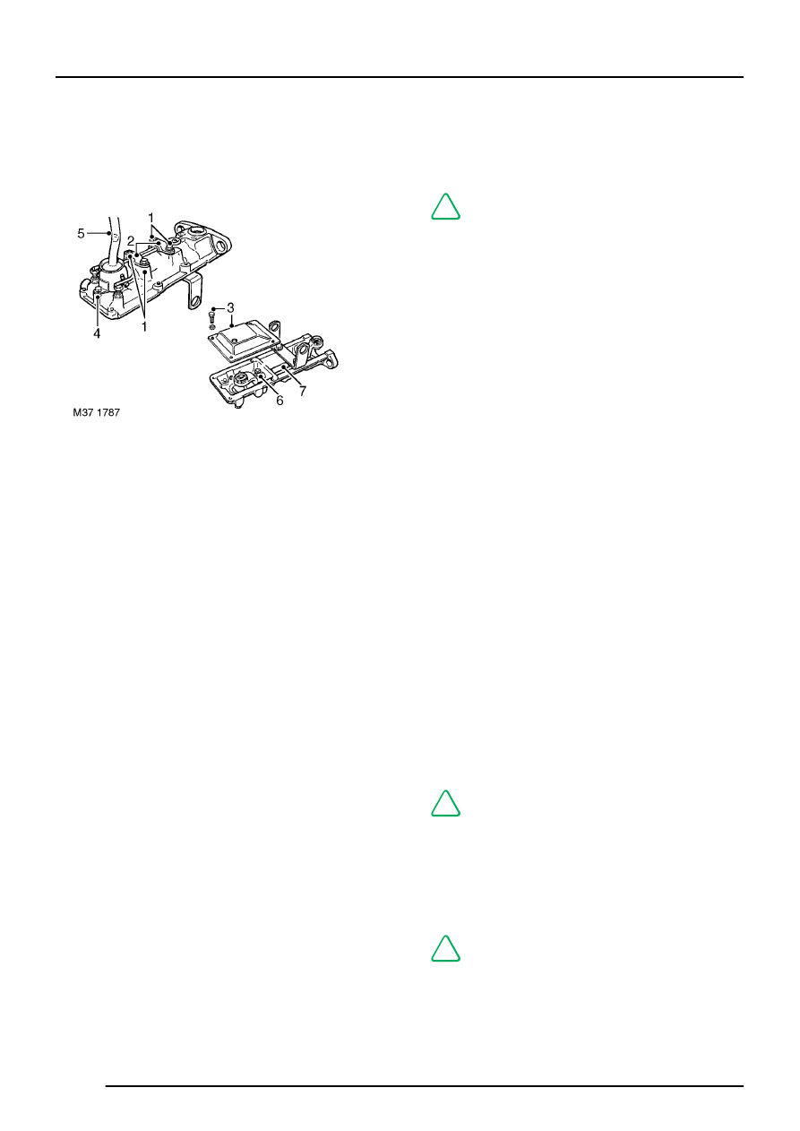
Remote gear change - Type C gearbox
Dismantle
1. Remove 2 bolts and 2 countersunk screws
securing bias spring bridge plates.
2. Remove bridge plates, bridge plate liners and
bias spring.
3. Remove 4 bolts and washers securing bottom
cover plate, remove plate.
4. Remove bolt securing gear lever cap, remove
cap.
5. Remove gear lever, recover anti-rattle spring
and plunger.
6. Remove pinch bolt securing selector rod yoke,
remove yoke.
7. Withdraw selector rod from remote housing.
8. Clean all components.
Inspection
1. Check selector rod bushes in remote housing
for wear.
NOTE: Bushes may be pressed in and out
of remote housing using a hand press and
suitable mandrel.
2. Check selector rod for wear, replace if
necessary.
3. Check anti-rattle spring for distortion and
plunger for wear; replace if necessary.
4. Check gear lever ball pin, cross pins, bushes
and selector rod yoke balls for wear and
replace if necessary. If yoke balls are worn,
remove and discard circlip, press ball and
seating out of yoke.
5. Lubricate replacement ball and seating with
multi-purpose grease and press into yoke;
secure using new circlip.
6. Check bias spring for distortion, replace if
necessary.
7. Check condition of mounting rubbers, replace
as a set if necessary.
Reassemble
1. Lubricate selector rod and bushes with multi -
purpose grease, insert rod in remote housing.
2. Lubricate gear lever ball pin and selector rod
yoke balls with multi-purpose grease.
3. Fit yoke to selector rod, fit pinch bolt and
tighten to 25 Nm (18 lbf.ft).
4. Assemble anti-rattle spring and plunger to gear
lever.
5. Fit gear lever ensuring ball pin is located in
yoke and anti-rattle spring and plunger are not
displaced.
6. Fit gear lever cap, fit bolt and tighten to 15 Nm
(11 lbf.ft).
NOTE: Do not fit bottom cover plate at this
stage.
7. Loosen bias spring adjustment bolt locknuts.
8. Fit bias spring, bridge plate liners and bridge
plates.
9. Fit bolts and countersunk screws and tighten to
25 Nm (18 lbf.ft).
NOTE: Final adjustment of bias spring is
carried out after remote gear change is
fitted to gearbox.