
Aviator 2WD V8-4.6L DOHC (2003)
If the marks are on opposite sides of' the driveshaft, the pinion flange is responsible for the vibration.
When installing or adjusting a pinion flange, the driveshaft runout must not exceed 0.076 mm (0.030 inch). When runout is within limits, recheck
for vibration at road speed. If vibration persists, balance the driveshaft.
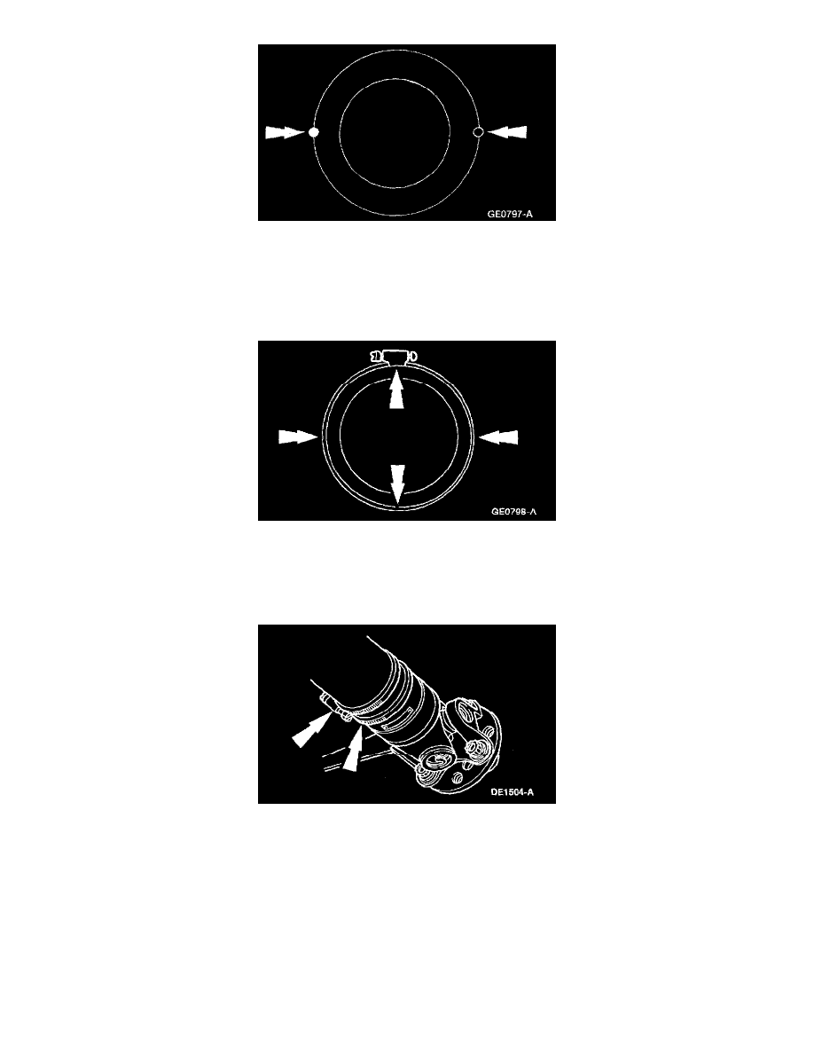
7. To balance the driveshaft, install one or two hose clamps on the driveshaft, near the ends. Position of the hose clamp head(s) can he determined by
trial-and-error.
8. Mark the rear of the driveshaft into four approximately equal sectors and number the marks 1 through 4. Install a hose clamp on the driveshaft with
its head at position No. 1.
Check for vibration at road speed. Recheck with the clamp at each of the other positions to find the position that shows minimum vibration. If two
adjacent positions show equal improvement, position the clamp head between them.
9. If the vibration persists, add a second clamp at the same position and recheck for vibration.