
Continental V8-4.6L DOHC VIN V (1998)
G12
Relay
The ISO relay can be tested using three No.10 (or larger gauge) jumper wires and 73 Digital Multimeter. Remove the relay to be tested from the power
distribution box, fuse junction panel, or individual connector.
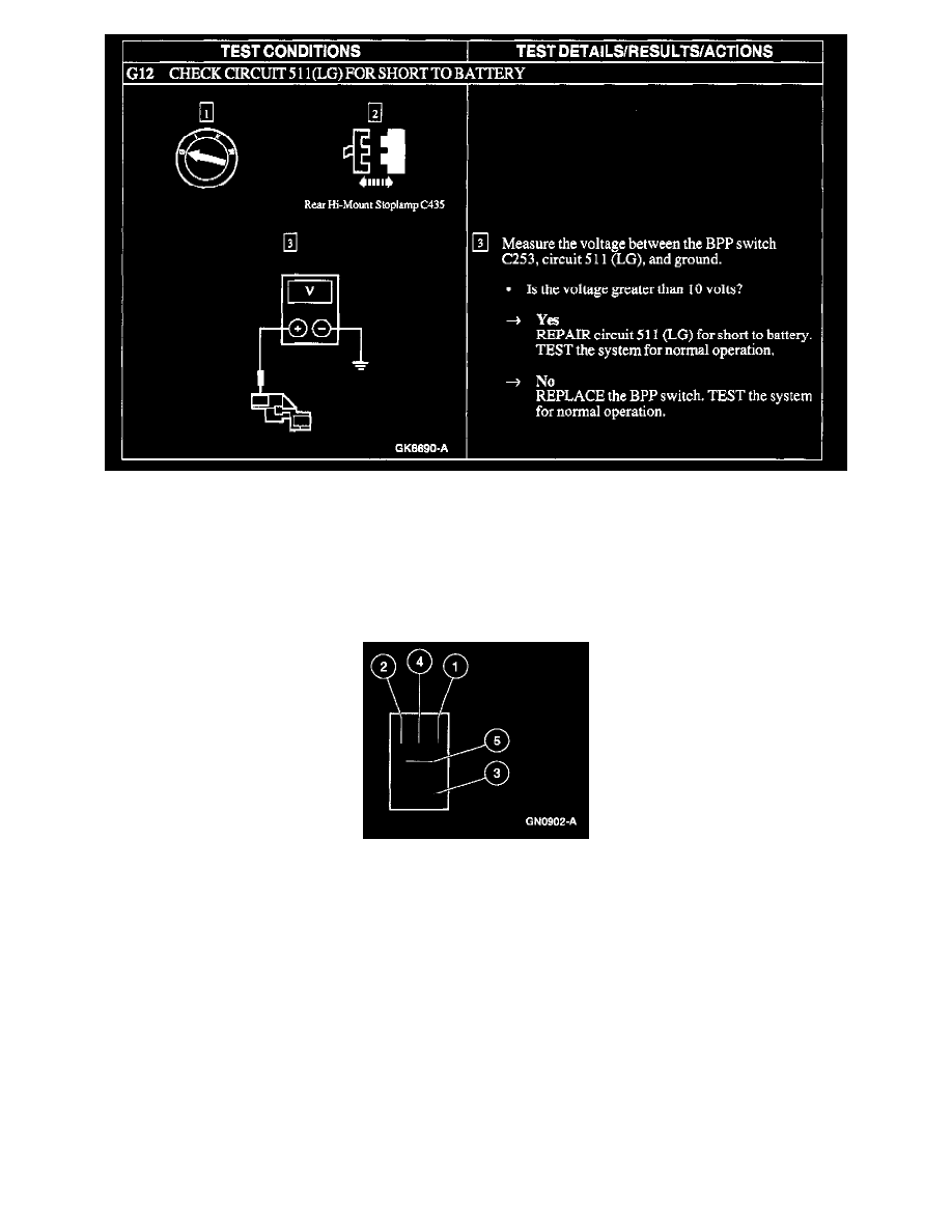
Micro ISO Relay
Use 73 Digital Multimeter to check for continuity between terminal 2 and all other terminals. If the resistance is 5 ohms or less between terminal 2 and
any other terminal, replace the relay. If the resistance is greater than 5 ohms, continue the test. Use two jumper wires to connect relay terminals 1 and 3
directly to the positive battery terminal. Set 73 Digital Multimeter in volts position and check for voltage at terminal 4. If battery voltage is not indicated,
replace the relay. If battery voltage is indicated, connect the third jumper wire to terminal 2, and ground the jumper wire to chassis ground. Check for
voltage at terminal 5. If battery voltage is not indicated, replace the relay.