
LS V8-3.9L VIN A (2003)
Test N5-N7
Normal operation
Each stoplamp is supplied battery voltage independently. Power from the battery junction box (BJB) flows through circuit 29S-LG6 (OG/YE) to
circuit 29S-LG6A (OG/YE) and then on to the high mounted stoplamp. Power from the BJB flows through circuit 29S-LF23 (OG) to the LH
stoplamp. Power from the BJB flows through circuit 29S-LF24 (OG/BK) to circuit 29S-LF23 (OG) and then on to the RH stoplamp. The stoplamps
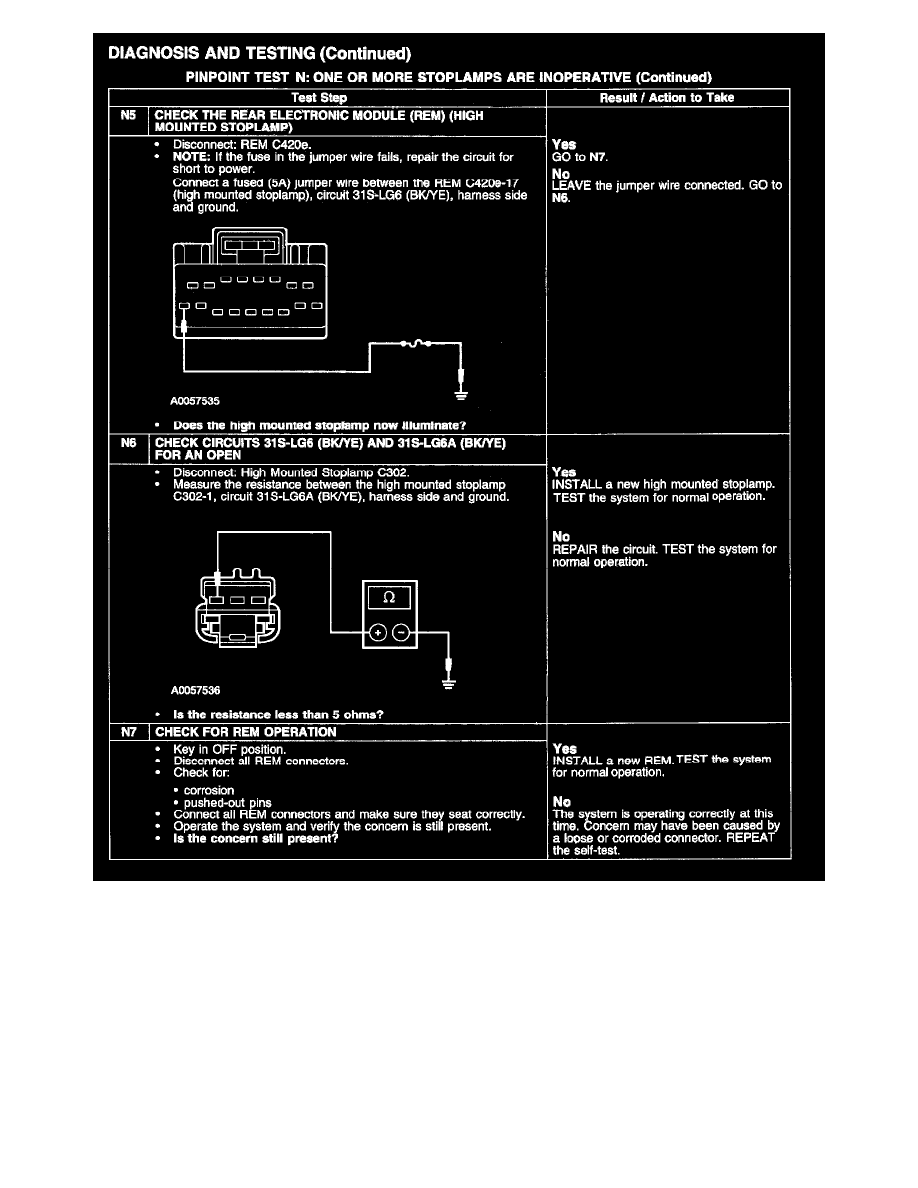
ground circuits are independently controlled by the rear electronic module (REM). When the REM receives voltage from the BPP switch (or IVD
module if equipped), the REM grounds circuits 31S-LG6 (BK/YE) (high mounted stoplamp), 31S-LG14 (BK/OG) (LH stoplamp) and 31S-LG21
(BK/GN) (RH stoplamp) to illuminate the stoplamps.
Possible causes
-
circuit 29S-LG6 (OG/YE) open
-
circuit 29S-LG6A (OG/YE) open
-
circuit 29S-LF23 (OG) open