
LS V8-3.9L VIN A (2003)
1. Remove and discard the tie strap from the digital TR sensor connector boot.
2. Slide the rubber boot back and disconnect the digital TR sensor connector.
Item 8: Transmission Range TR Sensor Installation Note
1. CAUTION: The digital transmission range sensor must fit flush against the boss on the case to prevent damage to the sensor.
Install the digital TR sensor and loosely install the screws.
Item 7: Transmission Range TR Sensor Screws Installation Note
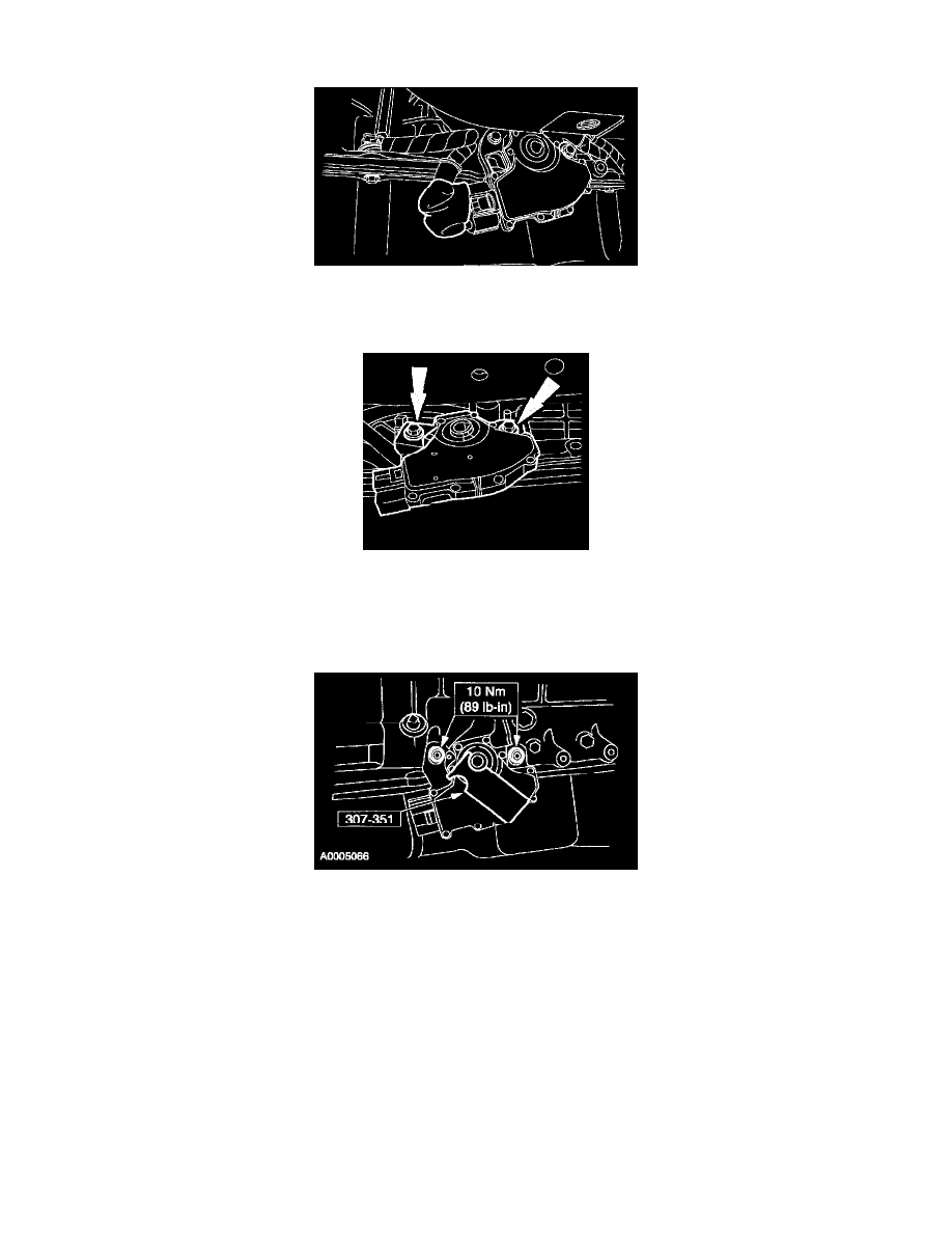
1. CAUTION: Tightening one screw before tightening the other may cause the sensor to bind or become damaged.
NOTE: The manual lever must be in the NEUTRAL position.
Using the special tool, align the digital TR sensor and tighten the screws in an alternating sequence.
Item 6: Transmission Range TR Sensor Electrical Connector Installation Note