
Mark LT 2WD V8-5.4L (2008)
Brake Booster (Part 2)
1. Disconnect the brake fluid level warning switch electrical connector.
2. CAUTION: For vehicles with 4.6L engines, brake booster vacuum hose is routed over the top of the exhaust gas recirculation (EGR)
valve; do not route it under the valve or damage to the hose may occur.
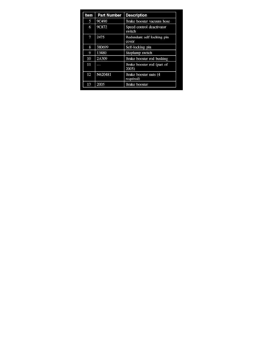
Disconnect the brake booster vacuum hose from the brake booster vacuum fitting.
3. Remove the 2 brake master cylinder nuts and position the master cylinder aside.
^
To install, tighten to 25 Nm (18 lb-ft).
4. CAUTION: Do not service the brake pedal or brake booster without first removing the stop lamp switch and speed control deactivator
switch. These switches must be removed with the brake pedal in the at-rest position. Switch plungers must be compressed for the switch
to rotate in the bracket. Attempting to remove the switch when the plunger is extended (during pedal apply) will result in damage to the
switch.
Remove the speed control deactivator switch. For additional information, refer to Cruise Control.
5. Remove the redundant self-locking pin cover and the self-locking pin.
6. Position the stop lamp switch, booster rod and bushing away from the brake pedal pin.
7. Remove the 4 brake booster nuts.
^
To install, tighten to 25 Nm (18 lb-ft).
8. CAUTION: Do not press, pull or otherwise move the brake pedal while installing the stop lamp switch or the speed control deactivator
switch. These switches must be installed with the booster push rod attached to the brake pedal and with the brake pedal in the at-rest
position. Installing these switches with the brake pedal in any other position will result in incorrect adjustment and may damage the
switches.
To install, reverse the removal procedure.