
Mark LT 2WD V8-5.4L VIN 5 (2007)
could result in pretensioner or air bag deployment and could result in personal injury.
-
To reduce the risk of personal injury, do not use any memory saver devices.
CAUTION: It is necessary to carry out the occupant classification sensor (OCS) system reset when a front passenger seat cushion is
disassembled, a new trim cover is installed, or an OCS service kit is installed. A scan tool is used to trigger the active command to carry out the
OCS system reset.
NOTE:
-
OCS system components (seat wiring harness, seat cushion frame, seat cushion foam pad, bladder with pressure sensor and electronic control unit
[ECU]) are calibrated to each other and are serviced as an assembly. OCS system components are not to be installed separately. If a new OCS
system, OCS system component or seat cushion foam pad are needed, a new OCS system service kit (seat cushion frame, seat cushion foam pad,
bladder with pressure sensor, seat wiring harness and ECU must be installed as an assembly.
-
To identify between a production OCS system and a service OCS system (OCS service kit) inspect the ECU electrical connector. A production
OCS system allows the disconnect of the ECU electrical connector. A service OCS system (OCS service kit) has the ECU electrical connector
glued to the ECU. It cannot and should not be disconnected or altered.
-
Repair is made by installing a new part only. If the new part does not correct the condition, install the original part and carry out the diagnostic
procedure again.
-
When installing a new OCS service kit, refer to Air Bag Systems for the OCS removal and installation procedure.
-
If a seat equipped with a supplemental restraint system (SRS) component is being serviced, the SRS must be depowered.
-
The air bag warning lamp illuminates when the restraints control module (RCM) fuse is removed and the ignition switch is ON. This is normal
operation and does not indicate a supplemental restraint system (SRS) fault.
-
The SRS must be fully operational and free of faults before releasing the vehicle to the customer.
-
For vehicles with power seats, position the seat cushion to its lower position before disconnecting the power seat.
-
Power seat shown, manual seat similar.
All seats
1. Remove the seat and depower the SRS.
2. If equipped, disconnect the power seat switch electrical connector.
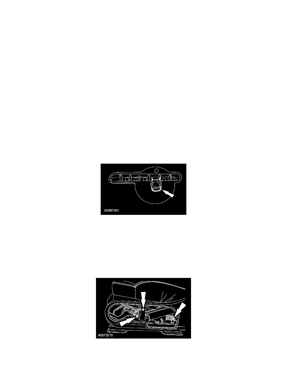
3. NOTE: Recline the seat backrest before removing the recliner handle to ease seat cushion assembly removal.
Remove the recliner handle.
-
Release the clip at the rear of side shield by detaching the clip from the metal bracket on the track. Partially flex the side shield at the rear to
obtain access to the recliner handle clip. Remove the recliner handle clip (shown removed for clarity) and the recliner handle.
4. If equipped, remove the lumbar knob.
5. Remove the side shield control panel.
6. If equipped, disconnect the memory seat switch electrical connector.
7. Remove the pin-type retainer from the front of the side shield.
8. Remove the 3 screws and the side shield.
9. Disconnect the safety belt buckle pretensioner electrical connector.