
Mark LT 2WD V8-5.4L VIN 5 (2007)
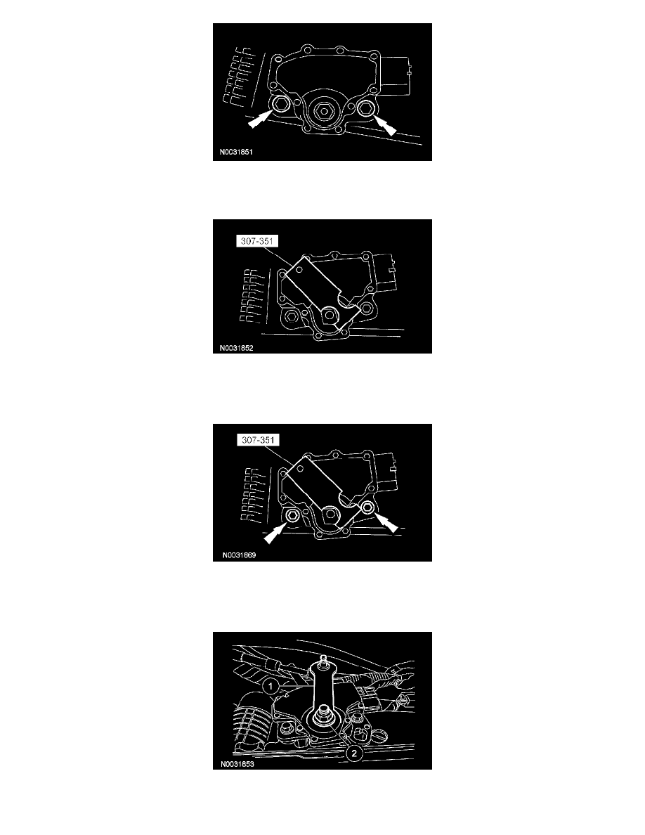
5. NOTE: The manual lever must be in the NEUTRAL position.
Using the special tool, align the digital TR sensor slots. The tool is designed to fit snug.
6. CAUTION: Tightening one bolt before tightening the other may cause the sensor to bind or become damaged.
Using the special tool, align the digital TR sensor and tighten the bolts in an alternating sequence.
^
Tighten to 9 Nm (80 inch lbs.).
7. Install the manual control lever.
1
Position the manual control lever.
2
Install a new manual lever shaft outer nut.
^
Tighten to 33 Nm (24 ft. lbs.).
8. NOTE: When installing the selector lever cable, make sure that the selector lever cable locking tabs are locked in place and the cable end is
snapped onto the ball stud. Press the selector lever cable into the bracket and listen for the cable to click in place. Pull back on the selector lever