
Mark LT 2WD V8-5.4L VIN 5 (2007)
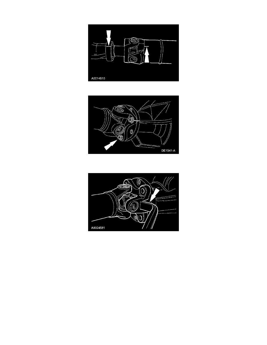
2. Index-mark the driveshaft flange to the pinion flange to maintain alignment during installation.
3. Index-mark the driveshaft to the extension housing to maintain alignment during installation.
4. Remove and discard the 4 driveshaft flange bolts.
^
To install, tighten to 103 Nm (76 ft. lbs.).
5. CAUTION: The driveshaft flange fits tightly on the flange pilot. Never hammer on the driveshaft or any of its components to disconnect the
driveshaft flange from the flange pilot. Pry only in the area shown with a suitable tool to disconnect the driveshaft flange from the flange pilot.
Using a suitable tool as shown, disconnect the driveshaft flange from the flange pilot and remove the driveshaft.
6. Plug the extension housing to prevent fluid loss.
7. CAUTION: The driveshaft flanges fits tightly on the pinion flange pilots. To make sure that the driveshaft flanges seat squarely on the pinion
flange pilots, tighten the driveshaft flange bolts evenly in a cross pattern.
CAUTION: If new bolts are not available, coat the threads of the original driveshaft flange bolts with Threadlock and Sealer.
NOTE: Align the index marks made during removal.
To install, reverse the removal procedure.
^
Install new driveshaft flange bolts.
Driveshaft - Front
Driveshaft - Front