
Mark VI V8-302 5.0L (1982)
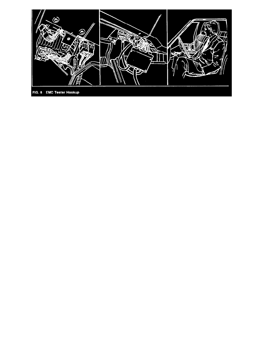
2. CONNECT TESTER between Control Module and its Harness (Fig 8).
-
Place TESTER on a clean cloth on passenger seat.
-
Unplug the two 20-pin harness connectors from the Control Module (under the dash). Connect the two 20-pin TESTER Harness leads to the
Control Module.
-
Connect the two 20-pin connectors removed from the Control Module to the Tester Harness lead.
3. CONNECT DVOM to TESTER. Place DVOM inside TESTER case.
-
Plug DVOM into TESTER jack (Tighten ring fingertight).
-
CHECK DVOM for proper operation (refer to procedures in this Section). Set DVOM to TESTER position.
IMPORTANT: DVOM external Test Leads MUST be removed from DVOM lacks in TESTER position.
4. BE SURE ALL CONNECTORS ARE SOLIDLY SEATED or incorrect displays will result during the tests.
5. RECONNECT vehicle battery-negative cable.
Tester Switches, Lights and Test Buttons Switches
The two Test Selector Switches select the specific function to be measured by the DVOM. A letter-number combination is used in the Test procedure
instructions to describe the switch settings to be used.
For example, "C-1" selects vehicle-battery voltage as the condition to be measured. With the DVOM in TESTER position, the DVOM will readout the
battery voltage. Other settings and what they measure are described in a list in this section.
Signal Lights (LEDs)
The SPEED LED lights if a speed signal is being sent from the speedometer to the Control Module.
The DISPLAY LED lights if incorrect information is being sent from the Control Module to the message center display pods...or if there is a possibly
malfunctioning message display pod.
Signal Simulators (Push Buttons)
In the Off positions, signals from the vehicle sensors are fed directly to the Control Module as if the Tester were not present...and the HI, LOW and
MSG buttons are inactive.
In the On positions, the tester generates signals and sends them to the Control Module when the HI, LOW and MSG buttons are pushed-simulating
various sensor signals to test the Control Module and the instrument display pod.
When the FUEL button is On, the signal sent by the Tester...
- In the HI position is: Fuel tank 1/2 full.
In the LOW position it is: Fuel tank 7/16ths full. (Neither is displayed.)
When the SPEED button is On, the signals sent by the Tester are...
- In the HI position: Speed 65.5 mph (105.4 Km/h)
- In the LOW position: Speed 6.1 mph 9.8 km/h)
When the DISPLAY button is On, each time the MSG (Message) button is pressed and released, the Tester sends a message to the Message Center
display pod.
(The eighth message is an incorrect data-format message that results in a blank display on the Message Center display pod-but causes the DISPLAY
SIGNAL LED to light up.)
SS and OHMS Push Buttons
Pressing the SS (Sensor Simulator) button in Test switch positions A-1 through A-1 2. B-1 through 12 and C-1 through 12 places a 200-ohms
resistance to ground in parallel with the circuit of the Control module selected by the Test Switches...in position E it causes the LOW Fuel Signal
button to generate a "Low fuel" signal. In other positions, the button is inactive.
Pressing the OHMS button switches the DVOM to read ohms (1999 ohms, full scale) instead of volts.
NOTE: Depressing the OHMS button with vehicle's battery connected may cause an incorrect ohms reading.