
Mark VII V8-302 5.0L HO (1986)
Brake Master Cylinder: Description and Operation
Brake Fluid Reservoir
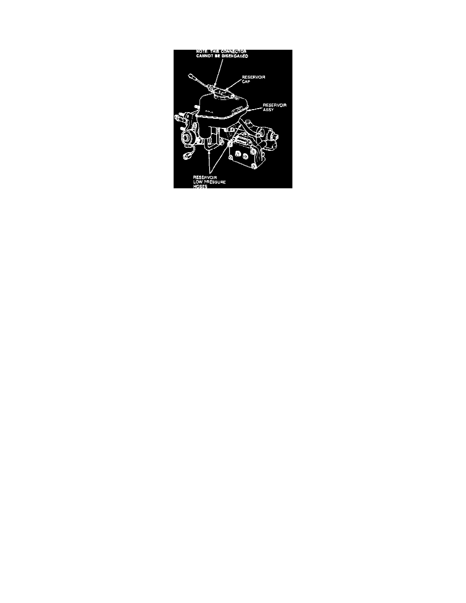
Fig. 6 Reservoir assembly
The reservoir assembly, Fig. 6, is a clear plastic container having two main chambers. Integral with the reservoir cap assembly are fluid level switches
with electrical connectors at either end. Two low pressure hoses lead from the reservoir, one to the hydraulic pump assembly and the other to the master
cylinder housing. The reservoir is mounted to the hydraulic unit with a screw and bracket and a push-in tube outlet seated in a grommet in the brake
booster housing.