
Mark VII V8-302 5.0L HO (1986)
Hydraulic Control Assembly - Antilock Brakes: Description and Operation
Hydraulic Assembly
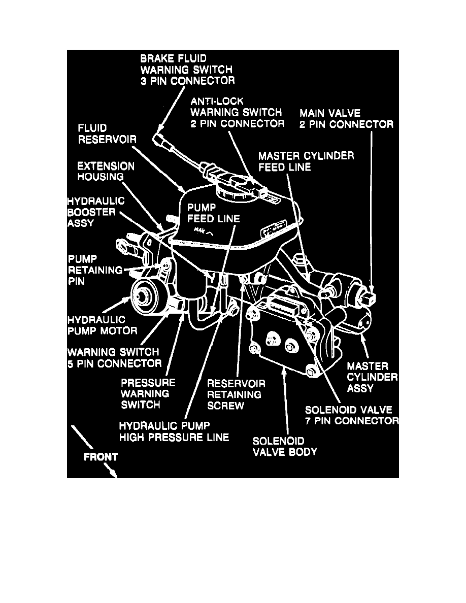
Fig. 2 Master cylinder & hydraulic booster assembly
The master cylinder and brake booster are arranged with the booster behind the master cylinder, Fig. 2. The booster control valve is installed in a bore
above the master cylinder centerline and is operated by a lever connected to the brake pedal pushrod.