
Mark VII V8-302 5.0L HO (1986)
4.
Turn pinion to full right position so that load slot is at pinion. Pinion will rotate without moving rack teeth when it is in the load slot.
5.
Remove pinion plug using tool No. T86P-3504-A or equivalent Fig. 1. Discard plug.
6.
Reverse tool and remove yoke plug. Discard plug.
7.
Remove spring and yoke.
8.
Remove pinion and bearing assembly by pushing out through the pinion plug opening Fig. 2. Tap lightly with plastic mallet if necessary.
9.
Remove rack from left side (pinion end).
10.
Pry out pinion shaft seal with a screwdriver and discard. Take care not to damage gear housing.
11.
Using tool No. T86P-3504-A or equivalent, clean up threads in the yoke plug bore and pinion plug bore.
12.
Wash all parts in suitable washing solution, and dry prior to reassembly. Do not submerge right end of housing tube containing polyurethane rack
bushing.
13.
Clean pinion and yoke threads with solvent to remove washing solution residue.
14.
Inspect rack bushing for wear or damage. If worn, remove by prying with a screwdriver, taking care not to damage gear housing rack tube.
Inspection
1.
Inspect gear housing for damage. Discard housing if yoke and pinion plug threads have previously re-staked (more than three yoke plug stakes
and more than two pinion plug stakes). Check threads for damage. Examine plastic bushing for wear or damage and ensure bushing tabs are
properly located in tube slots. Check needle bearing for wear and roughness. Replace housing assemble if any of its components are worn or
damaged, except for the rack bushing which can be replaced.
2.
Examine rack for corrosion, straightness, tooth wear or damage. Check threads in end of rack. Replace rack as required.
3.
Inspect pinion rack for corrosion at seal area and below. Lightly oil the pinion ball bearing and check for bearing wear and roughness. Examine
pinion shaft for straightness. Check pinion teeth for wear, cracking, scoring, pitting or breakage. Replace pinion as required.
4.
Inspect end of rack for burrs. File ends lightly, if necessary, to provide a square, flat surface for tie rod sockets.
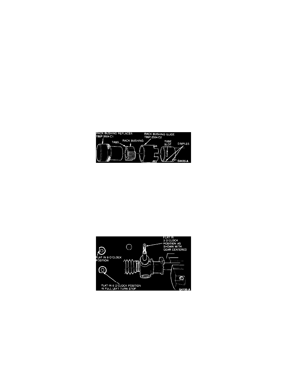
Fig. 3 Rack bushing guide alignment
Assembly
1.
If rack bushing was not removed, proceed to Step 7.
2.
Align three slots of Rack Bushing Guide T86P-3504-C2 or equivalent over dimples in rack tube Fig. 3. Align extra slot exactly over one of the
tube slots.
3.
Lubricate new rack bushing outer diameter with steering gear grease C3AZ-19578-A or equivalent.
4.
Insert new rack bushings into tool so tabs align with grooves in tool. Tabs must be up (away from rack housing).
5.
Push bearing into rack tube with tool No. T86P-3504-C1 or equivalent using hand pressure until tool bottoms. Remove guide tool. Re-apply hand
pressure with replacer tool to fully seat tabs in slots, if necessary. Use only enough force to fully engage tabs in slots.
6.
Inspect installation of rack bushing to ensure tabs are engaged into slots. If tabs are not properly positioned, dislodgement of bushing may occur.
7.
Fill rack teeth spacers with steering gear grease C3AZ-19578-A or equivalent. Coat remainder of rack with light coat of grease.
Fig. 4 Pinion flat positioning
8.
Pack pinion needle bearing with steering gear grease C3AZ-19578-A or equivalent. Pack some grease into cavity inboard of rack bushing. Also,
lightly coat inner diameter of rack bushing with grease.
9.
Install rack into housing from left end (pinion end) and center load slot in pinion bore.
10.
Pack pinion teeth and coat needle bearing journal with steering gear grease C3AZ-19578-A or equivalent. Pack pinion ball bearing with grease.
11.
Install pinion shaft and bearing assembly from bottom through load slot in rack.
12.
Install pinion plug and torque to 53---73 ft. lbs.
13.
Install left tie rod assembly to rack. Seat it against rack but do not tighten at this time. This establishes the left turn stop position of the rack.
14.
Mount gear housing in vise with pinion in approximately in-vehicle position. Hold pinion with flat in 9 o'clock position, Fig. 4, while pushing
rack into housing. Jiggle rack to engage rack to pinion and to start rack into rack bushing. Push rack all the way in. The input shaft flat should stop
in the 6 o'clock position when the left ball joint contacts the housing (full left turn stop). Repeat the procedures at the load slot, deviating from the