
Mark VII V8-302 5.0L VIN F FI (1987)
Brake Fluid Accumulator: Description and Operation
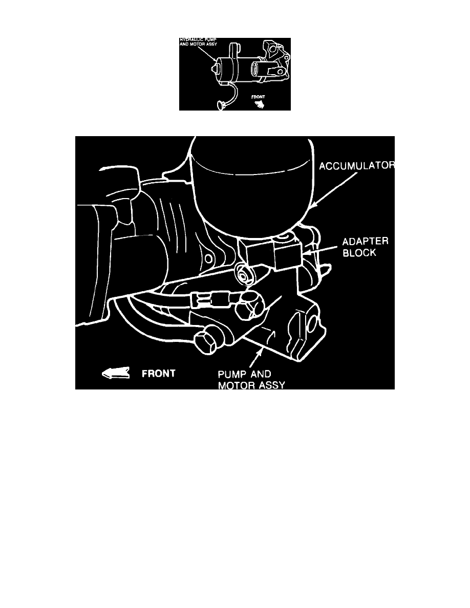
Fig. 3 Hydraulic pump assembly
Fig. 4 Accumulator assembly
The electric high-pressure pump, Fig. 3, runs for short periods to charge the hydraulic accumulator which supplies the service brake system.The
accumulator, Fig. 4, is a gas filled pressure chamber which is part of the pump and motor assembly. The entire assembly is shock-mounted to the master
cylinder and booster.
NOTE: If pump motor runs continuously for 20 minutes, a thermal safety switch (located in the motor) will shut motor off. A 2 to 10 minute cool-down
is typical before operation can resume.