
Mark VIII V8-4.6L DOHC (1996)
Electronic Brake Control Module: Diagrams
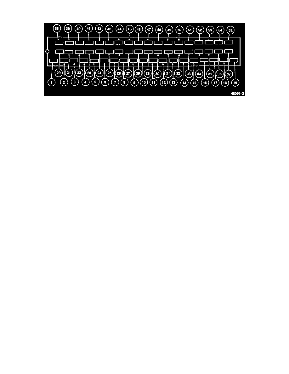
Connector
Pin Number
Circuit
Circuit Function
1
651 (BK/Y)
Ground
2
498 (PK)
LF Outlet Valve Output
3
532 (O/Y)
Switched Power
4
Not Used
5
467 (GY/Y)
Anti-Lock Brake Pedal Sensor Switch Input
6
Not Used
7
Not Used
8
550 (Y/LG)
Fluid Level Switch Input
9
Not Used
10
Not Used
11
Not Used
12
Not Used
13
Not Used
14
Not Used
15
539 (PK/LB)
Anti-Lock Brake Motor Relay Output
16
Not Used
17
Not Used
18
492 (BR)
RR Outlet Valve Output
19
651 (BK/Y)
Ground
20
495 (T)
LF Inlet Valve Output
21
497 (W)
RF Outlet Valve Output
22
Not Used
23
606 (W/LB)
Anti-Lock Data Link Connector Input
24
Not Used
25
959 (GY)
TA ON/OFF Switch
26
493 (BK/PK)
Switch Reference Voltage Output
27
524 (PK/BK)
RR Brake Sensor Input (Low)
28
519 (LG/PK)
LR Brake Sensor Input (Low)
29
516 (Y/BK)
RF Brake Sensor Input (Low)
30
522 (T/BK)
LF Brake Sensor Input (Low)
31
462 (P)
Pump Motor Speed Sensor Input
32
511 (LG)
Stoplight Switch Input
33
532 (O/Y)
Switched Power
34
599 (PK/LG)
Anti-Lock Brake Relay Output
35
537 (T/Y)
Keep Alive Power Traction Assist
36
499 (GY/BK)
Rear Left Outlet Valve Output
37
601 (LB/PK)
Special Valve No. 1 Traction Assist
38
510 (T/R)
RF Inlet Valve Output
39
Not Used
40
677 (LB)
Special Valve No. 2 Traction Assist
41
Not Used
42
Not Used
43
Not Used
44
960 (BK/LB)
TA Indicator Output
45
523 (R/PK)
RR Brake Sensor Input (High)