
Mark VIII V8-4.6L DOHC (1996)
Wheel Speed Sensor: Description and Operation
Fig. 5 Front Wheel Sensor Assembly.
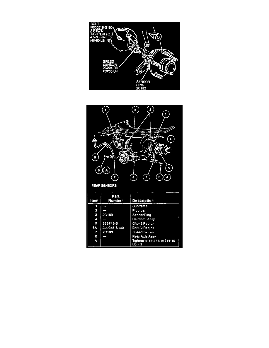
Fig. 6 Rear Wheel Sensor Assembly.
This system, Figs. 5 and 6, uses four sets of variable reluctance sensors and toothed speed indicator rings to determine the rotational speed of each
wheel. The sensors operate on magnetic induction principle. For example, as the teeth on the speed indicator ring rotate past the stationary sensor, a
signal proportional to the speed of the rotation is generated and transmitted to the ABS module (Electronic Control Unit (ECU)) through a coaxial cable.
The front sensors are attached to the suspension knuckles and the speed indicator rings are pressed onto the outer constant velocity joints. The rear
sensors are attached to the rear caliper anchor plate and the speed indicator rings are pressed onto the rear wheel hub assemblies. The sensors and the
speed indicator rings are serviced individually.