
Mark VIII V8-4.6L DOHC (1996)
34. Remove four bolts retaining RH and LH IMRC assemblies to intake manifold and remove IMRC assemblies.
NOTE: Intake manifold upper gaskets must be replaced when intake manifold retaining bolts have been loosened.
35. Remove intake manifold upper gaskets and all load limiting spacers from RH and LH IMRC assemblies and discard.
36. Remove lower intake manifold gaskets from cylinder heads and discard.
37. Remove EGR valve gasket and discard. Clean EGR valve gasket sealing surface on both EGR valve and intake manifold.
INSTALLATION
NOTE: If new intake manifold or IMRC assembly is being installed, transfer all necessary components onto new intake manifold or IMRC assembly
using new gaskets.
1. Clean and inspect all sealing surfaces. Upper sealing surfaces or IMRC assemblies and intake manifold mating surfaces should be cleaned with a
suitable solvent to remove adhesive residue. Inspect intake manifold mating surfaces and upper IMRC assembly surfaces to ensure that no load
limiting spacers (washers) are stuck to the sealing surfaces. The load limiting spacers are part of the intake manifold upper gasket. New load
limiter spacers will be included with the replacement intake manifold upper gasket as an assembly.
2. Remove protective paper from adhesive backing on intake manifold upper gasket and install onto top of RH IMRC assembly using tapered pins at
end bolt hole locations for proper gasket alignment. Repeat same procedure for LH assembly.
3. Assemble IMRC assemblies to intake manifold and install four IMRC retaining bolts. Finger tighten bolts.
4. Install fuel injection supply manifold onto fuel injectors and install four retaining bolts. Tighten to 8-12 Nm (71-106 lb in). Install two fuel
pressure regulator bracket retaining screws. Tighten to 8-12 Nm (71-106 lb in).
5. Position new intake manifold gaskets onto cylinder heads using integral locating pins to align gaskets.
6. Place intake manifold under fuel charging wiring and connect fuel charging wiring to idle air control valve and throttle position sensor. Connect
wiring clip to idle air control valve retaining stud.
7. Move intake manifold into position and install new EGR valve gasket and two EGR valve retaining bolts. Finger tighten bolts.
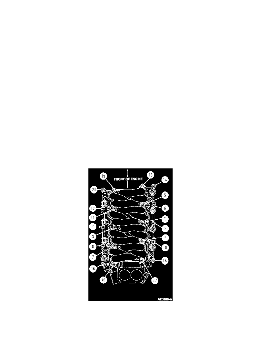
8. Install 10 longer bolts and stud bolts in outer bolt holes of intake manifold. Do not tighten.
9. Install 10 shorter bolts and stud bolts in inner bolt holes of intake manifold. hand tighten all 20.
10. Tighten fasteners in numerical torquing sequence as follows:
-
Fasteners 5,7,9 and 11 to 12-15 Nm (8.8-11.0 lb ft).
-
All other fasteners to 18-22 Nm (13-16 lb ft).
-
Then tighten all fasteners in numerical sequence by rotating an additional 85-95 degrees.
11. Tighten four intake manifold to IMRC retaining bolts A-D in (see diagram) to 8-10 Nm (71-89 lb in). Tighten fasteners A through D in
alphabetical sequence by rotating 85-95 degrees.