
MKS AWD V6-3.7L (2009)
The audio Digital Signal Processing (DSP) module communicates with the scan tool through the Medium Speed Controller Area Network (MS-CAN).
Circuits VDB06 (GY/OG) (MS-CAN +) and VDB07 (VT/OG) (MS-CAN -) provide the network connection to the audio DSP module. Voltage for the
DSP module is provided by circuits SBP38 (BN/RD) and SBP40 (VT/RD). Circuit GD149 (BK/GY) provides ground.
This pinpoint test is intended to diagnose the following:
-
Fuse
-
Wiring, terminals or connectors
-
Audio DSP module
PINPOINT TEST L: THE AUDIO DSP MODULE DOES NOT RESPOND TO THE SCAN TOOL
NOTICE: Use the correct probe adapter(s) when making measurements. Failure to use the correct probe adapter(s) may damage the
connector.
-------------------------------------------------
L1 CHECK THE AUDIO DSP MODULE VOLTAGE SUPPLY CIRCUITS FOR AN OPEN
-
Ignition OFF.
-
Disconnect: Audio DSP Module C4326b.
-
Ignition ON.
-
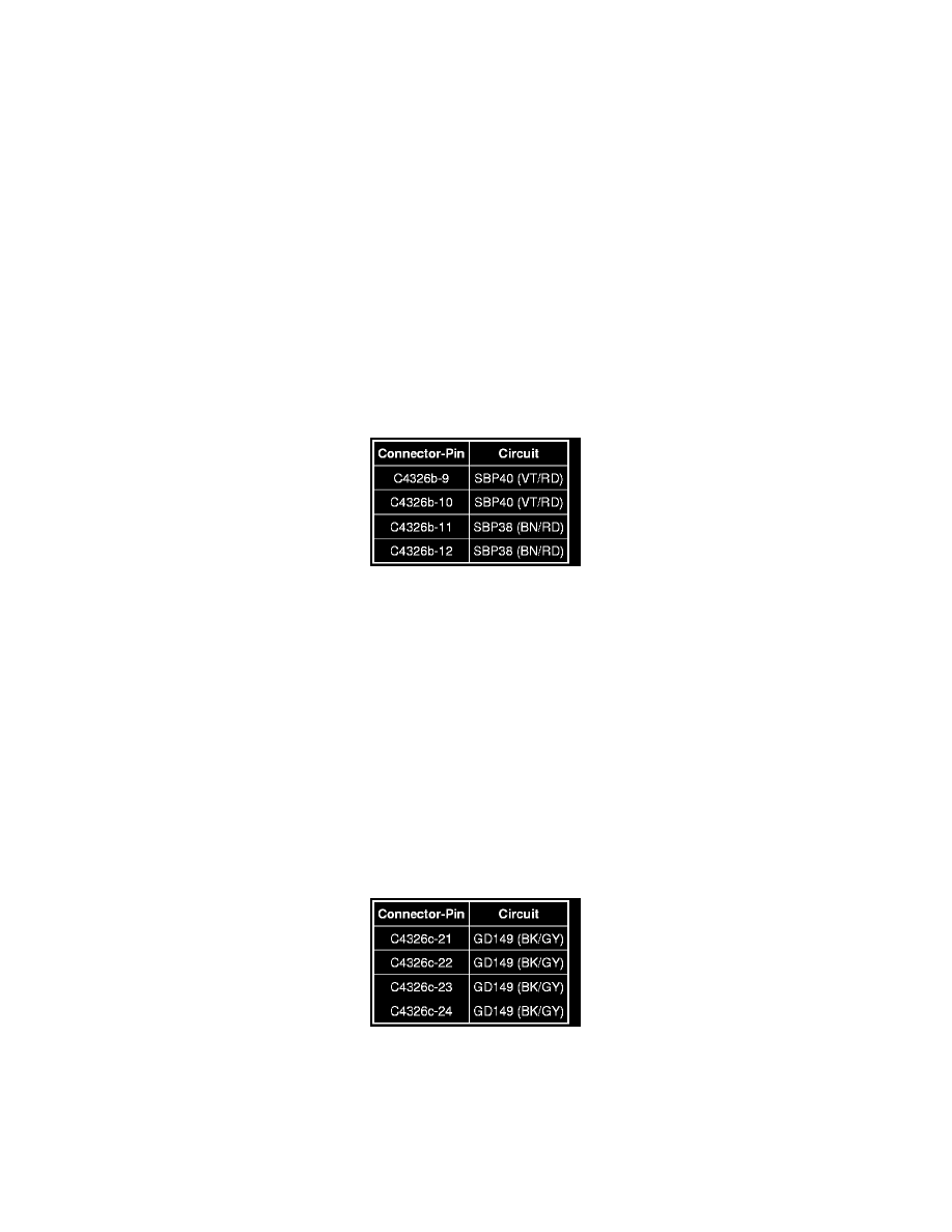
Measure the voltage between the audio DSP module, harness side and ground as follows:
-
Are the voltages greater than 10 volts?
Yes
GO to L2.
No
VERIFY the Smart Junction Box (SJB) fuse 38 (20A) or fuse 40 (20A) is OK. If OK, REPAIR the circuit in question. If not OK, REFER to the Wiring
Diagrams to identify the possible causes of the short circuit. CLEAR the DTCs. REPEAT the network test with the scan tool.
-------------------------------------------------
L2 CHECK THE AUDIO DSP MODULE GROUND CIRCUITS FOR AN OPEN
-
Ignition OFF.
-
Disconnect: Audio DSP Module C4326c.
-
Measure the resistance between the DSP module, harness side and ground as follows:
-
Are the resistances less than 5 ohms?
Yes
GO to L3.
No