
MKS AWD V6-3.7L (2009)
provided by circuit CBX01 (GN/RD). Circuit GD903 (BK/WH) provides ground.
This pinpoint test is intended to diagnose the following:
-
Fuse
-
Wiring, terminals or connectors
-
DCSM
PINPOINT TEST P: PINPOINT TEST P: THE DCSM DOES NOT RESPOND TO THE SCAN TOOL
WARNING: Remove restraint system diagnostic tools from the vehicle prior to road testing. If tools are not removed, the supplemental
restraint system (SRS) device may not deploy in a crash. Failure to follow this instruction may result in serious personal injury or death in a
crash and possibly violate vehicle safety standards.
NOTICE: Use the correct probe adapter(s) when making measurements. Failure to use the correct probe adapter(s) may damage the
connector.
NOTE: If a seat equipped with a Supplemental Restraint System (SRS) component is being serviced, the SRS must be depowered. Refer to Air Bag
Systems.
NOTE: The air bag warning lamp illuminates when the Restraints Control Module (RCM) fuse is removed and the ignition switch is ON. This is normal
operation and does not indicate a SRS fault.
NOTE: The SRS must be fully operational and free of faults before releasing the vehicle to the customer.
-------------------------------------------------
P1 CHECK THE DCSM VOLTAGE SUPPLY CIRCUITS FOR AN OPEN
-
Ignition OFF.
-
For vehicles with seat side air bags, carry out the following:
-
Depower the SRS. Refer to Air Bag Systems.
-
Disconnect the driver seat side air bag module.
-
Connect the restraint system diagnostic tool to the driver seat side air bag module.
-
Disconnect the passenger seat side air bag module.
-
Connect the restraint system diagnostic tool to the passenger seat side air bag module.
-
Connect the battery ground cable.
-
Disconnect: DCSM C3265a.
-
Ignition ON.
-
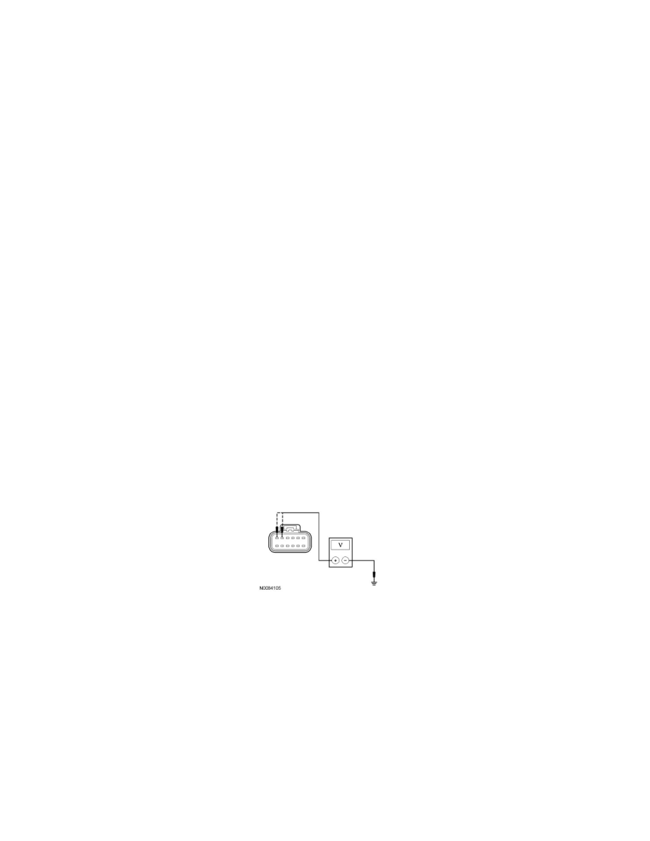
Measure the voltage between the DCSM C3265a-E, circuit CBX01 (GN/RD), harness side and ground; between the DCSM C3265a-F, circuit
CBX01 (GN/RD), harness side and ground.
-
Are the voltages greater than 10 volts?
Yes
GO to P2.
No
VERIFY the Battery Junction Box (BJB) fuse 22 (30A) is OK. If OK, REPAIR the circuit in question. If not OK, REFER to the Wiring Diagrams to
identify the possible causes of the short circuit. CLEAR the DTCs. REPEAT the network test with the scan tool.
-------------------------------------------------
P2 CHECK THE DCSM GROUND CIRCUIT FOR AN OPEN
-
Ignition OFF.
-
Measure the resistance between the DCSM C3265a-M, circuit GD903 (BK/WH), harness side and ground.